1. System Installation Requirements
1-41
TI 32P01J10-01EN
I O M
I O M
I O M
I O M
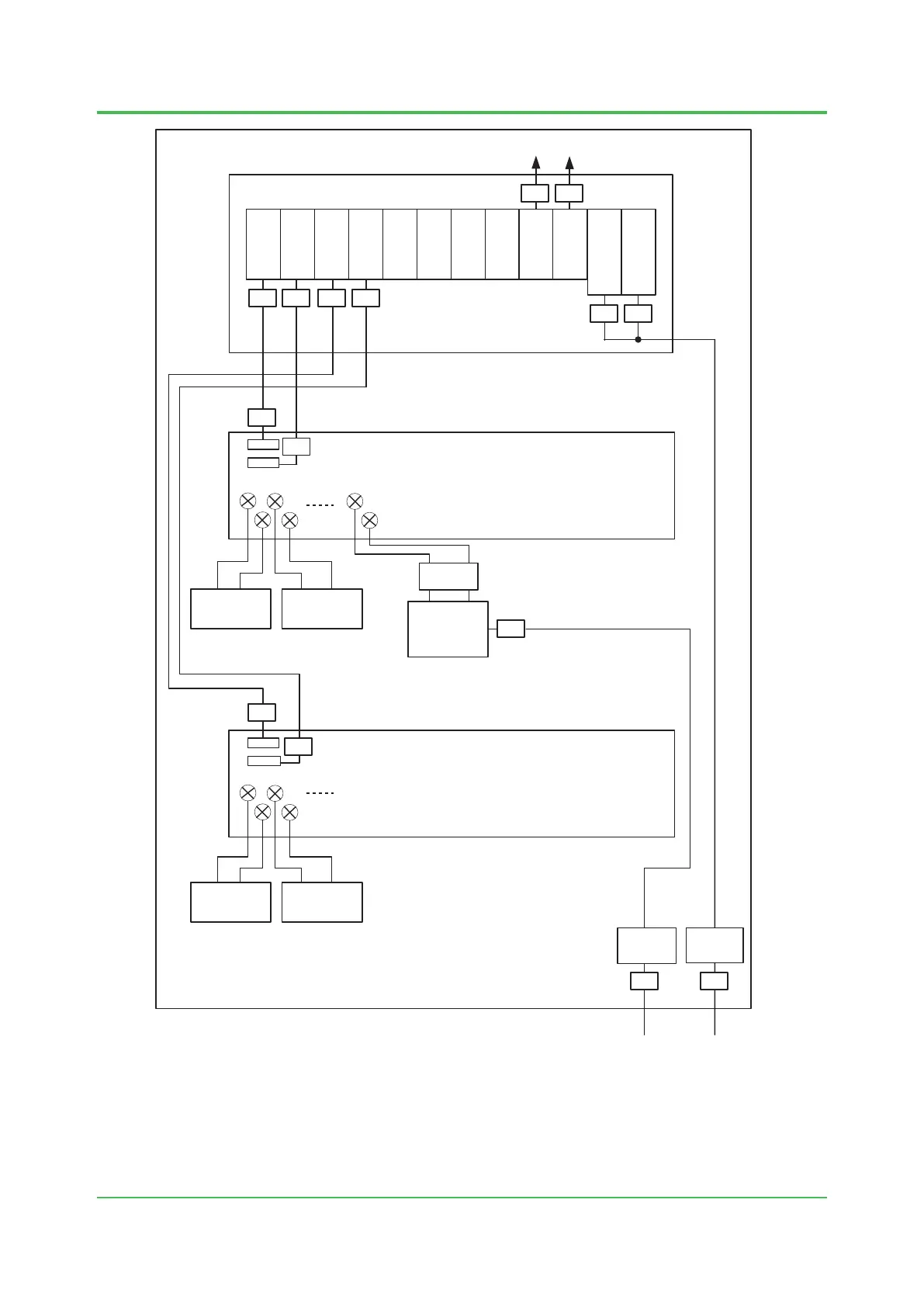
SNB10D
Cabinet
SSB401
SSB401
for SEC402/SEC401
Terminal Board for Digital I/O / Relay Board
External
Power
Supply (*1)
Field
Device 1
Field
Device 2
(7)
Terminal Board for Analog I/O
Field
Device 3
Field
Device 4
Noise
Filter (*2)
Noise
Filter
A n a l o g
I / O
D i g i t a l
I / O
A n a l o g
I / O
D i g i t a l
I / O
F010804.ai
SPW48
SPW48
(8) (9)
(6)
(19)
(20)
(20)
(19)
(2) (2)
(12) (12)
(17) (17) (18) (18)
Note: IOM is abbreviation of Input/Output Modules.
Note: Figures in ( ) show the locations listed in “Table Cables that Need Ferrite Cores to be
Attached to, and Ferrite Core Models and Quantities”. It is NOT a number of ferrite core.
*1: When supplying 24 V DC from outside of a cabinet, it isn’t necessary to install “External Power Supply”.
But, when not installing this “External Power Supply”, it’s necessary to install (6) and (7).
*2: This noise lter is for the external power supply unit. Regarding necessity of the noise lter, please follow directions on
instructions for marine standards of this external power supply unit.
Figure Locations of Ferrite Core Installation for Input/Output Modules, Terminal Boards and Relay
Boards
Mar. 29, 2019-00
 Loading...