2-30
IM WT310E-02EN
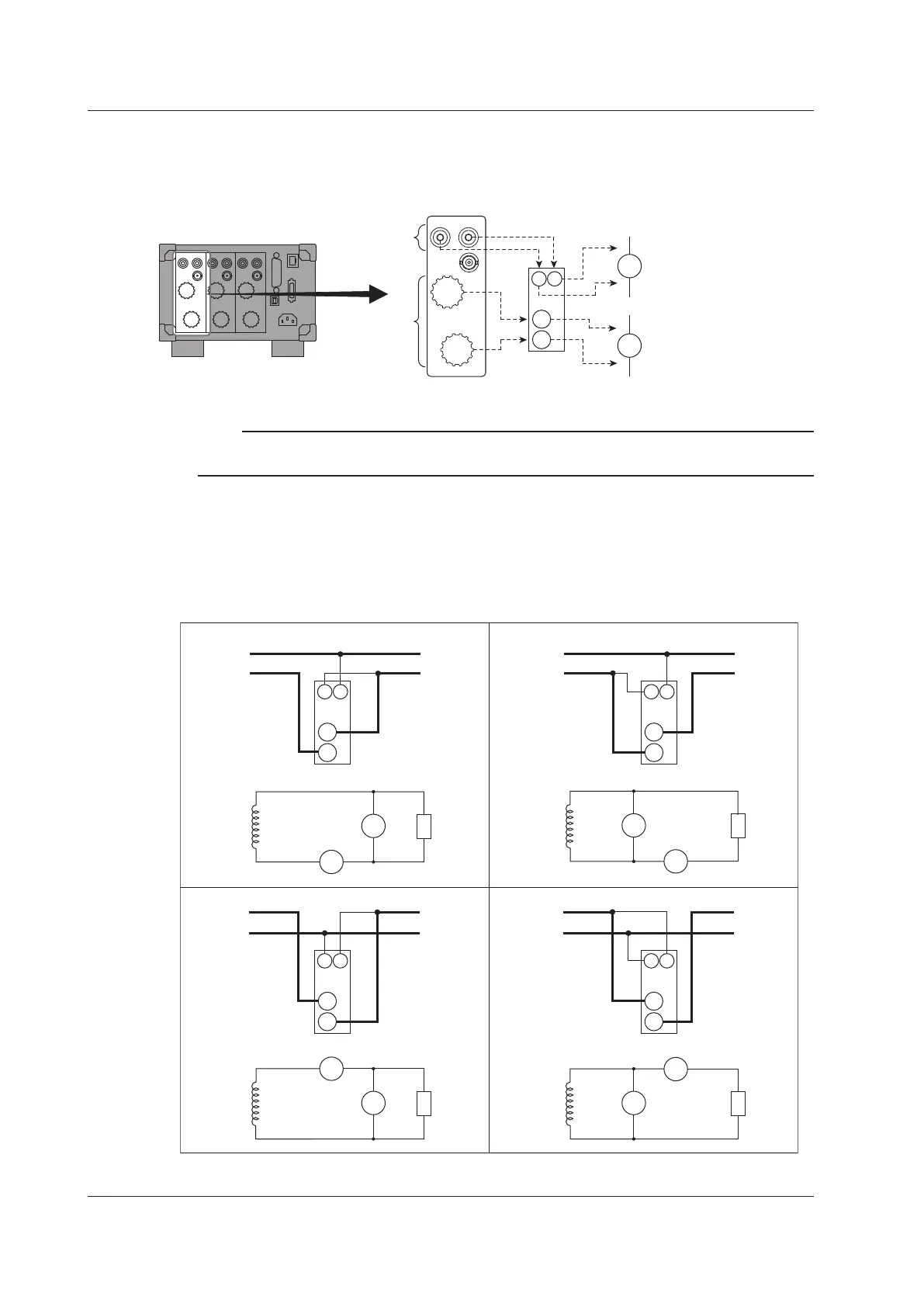
Connecting to the WT332E/WT333E
In the wiring examples that follow, the WT332E/WT333E input elements, voltage input terminals, and
current input terminals are simplified as shown in the following figure.
VOLTAGE
±
±
CURRENT
EXT
C
±
V
±
U1
I1
C
V
±
±
Voltage input
terminals
Current input
terminals
The voltage input terminals
and current input terminals of
input element 1 are labeled
as U1 and I1, respectively.
C: CURRENT terminal
WT332E/WT333E
Note
The thick lines on the wiring diagrams are the parts where the current flows. Use wires that are suitable for
the current levels.
Wiring Examples of Single-Phase, Two-Wire Systems (1P2W)
The following wiring example shows how to configure the wiring to connect to input element 1. To
configure the wiring for other input elements, substitute the numbers in the figures with the appropriate
element numbers.
C
±
V
±
C
±
V
±
C
±
V
±
SOURCE
LOAD
U1
I1
C
V
LOAD
U1
V
I1
C
SOURCE
SOURCE
LOAD
Input element 1
SOURCE
LOAD
Input element 1
±
±
±
±
SOURCE
LOAD
Input element 1
SOURCE
LOAD
Input element 1
SOURCE
LOAD
U1
I1
C
V
SOURCE
LOAD
U1
I1
C
V
±
±
±
±
C
±
V
±
2.9 Wiring the Circuit under Measurement for Direct Input

 Loading...


