3-4
All Rights Reserved. Copyright © 2004, Yokogawa Electric Corporation
<Toc> <Ind>
TI 11M12A01-01E
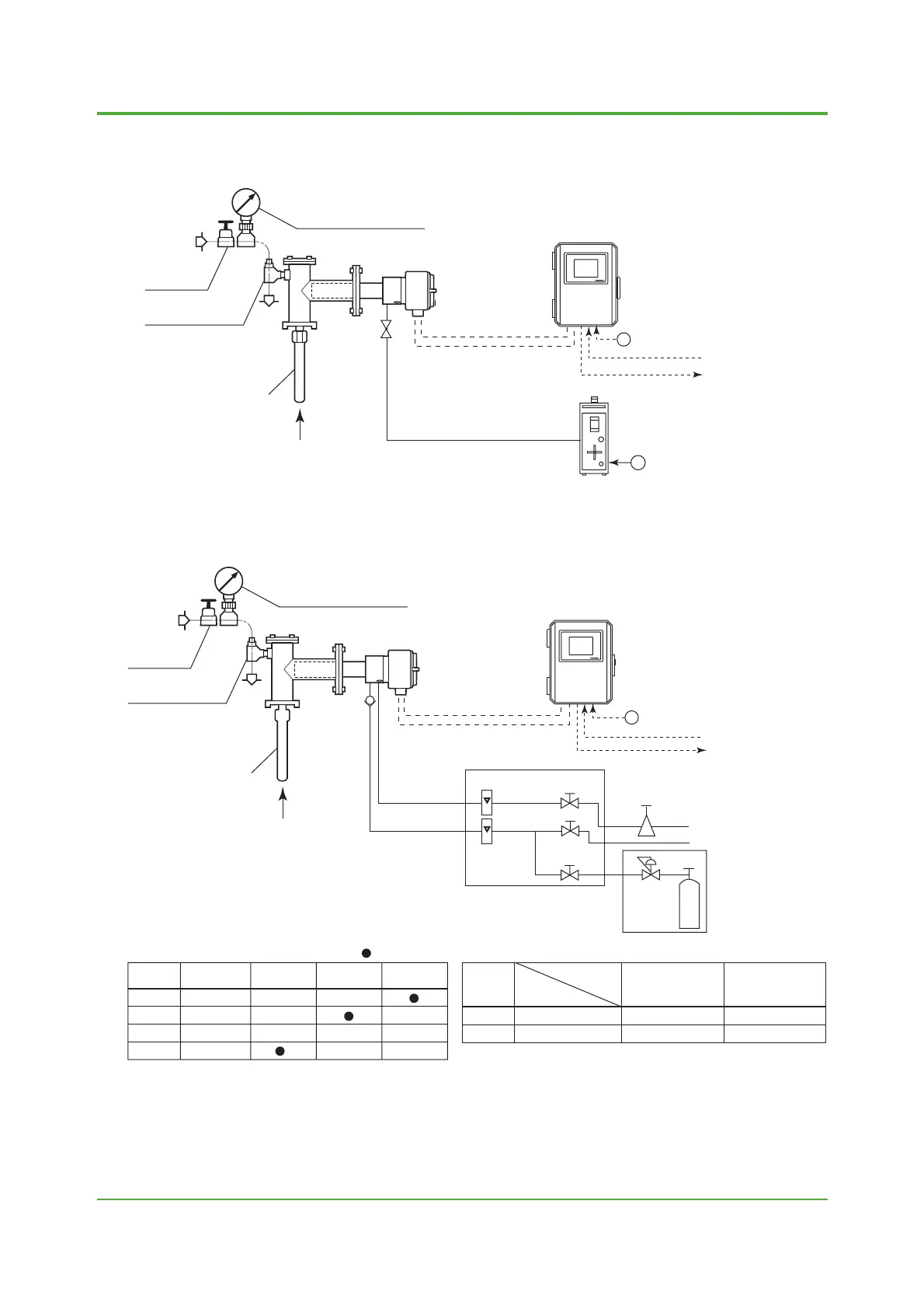
3. System Configurations
(4) Type: H1 (simple measurement system)
EXA
ZR402G
⬃
⬃
F0304.EPS
<2> ZR402G Converter
<1> High-temperature detector ZR22G-015
Calibration gas
<3> ZO21S Standard gas unit
100 to
240 V AC
Contact input
Analog output,
contact output
(Digital output HART)
Signal
(6-core shield cable)
Air supply
(1.5kgf/cm
2
)
Needle
valve
*2
*3
Ejector ASSY
Pressure gauge ASSY
Heater (2-core)
(5) Type: H2 (no auto calibration, no safety purge)
F0305.EPS
Check
Vertical downward
mounting
Horizontal
mounting
Mounting
orientation
Maximum
temperature (°C)
800
1400
SUS310S
—
SUS310S
SiC
Note 3: Selection of high temperature probe material
: Necessary
Check
Needle
valve
*1
Ejector
ASSY
*2
Ejector
ASSY
*3
Pressure
kPa
–0.5
–0.5 to 0.05
0.05 to 0.5
0.5 to 5
*1: K9473XH/K9473XJ
*2: E7046EC/E7046EN
*3: consult with YOKOGAWA
Note 2: Selection of Needle valve or Ejector
⬃
EXA
ZR402G
<2> ZR402G Converter
<3> ZA8F flow setting unit
100 to
240 V AC
Air Set
Instrument air
Calibration gas
Regulator
Reference
gas
Flowmeter
Needle
valve
Zero gas
cylinder
Span gas
Contact input
Analog output,
contact output
(Digital output HART)
Signal
(6-core shield cable)
Heater (2-core)
<1> High-temperature detector ZR22G-015
Air supply
(1.5kgf/cm
2
)
Needle
valve
*2
*3
Ejector ASSY
Pressure gauge ASSY
May 31,2004-00
 Loading...


