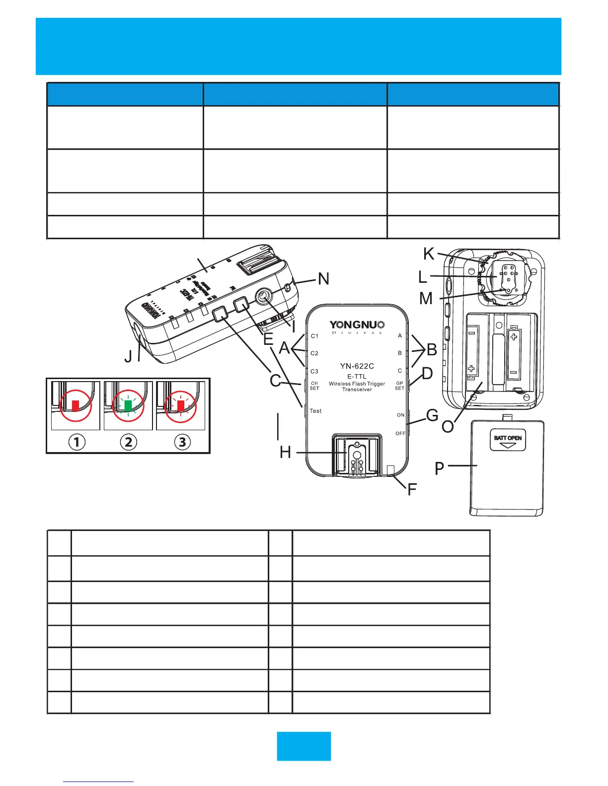
A
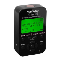
Channel indicator (p.8)
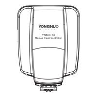
I PC port(p.23)
B
Group indicator (p.8/9)
J AF assist beam emitter(p.24)
C Channel setting button (p.8/9) K Locking ring (p.6/7)
D Group setting button(p.8/9) L Mounting foot(p.6/7)
E Test button(p.9/10) M locking pin(p.6)
F State indicator(p.5) N Eyelet
G Power switch(p.8) O Battery compartment cover(p.6)
H Hot shoe(p.6/7) P Battery compartment(p.6)
Indicator Blinking Keep Lighting
Channel Indicator
Communicating
(Remote control mode)
Mix Control Mode
Group Indicator
Firing group or
receiving group
Testing
Communicating
State Indicator(green) TX Communicating Testing Communicating
State Indicator(red) RX Communicating Standby State
 Loading...