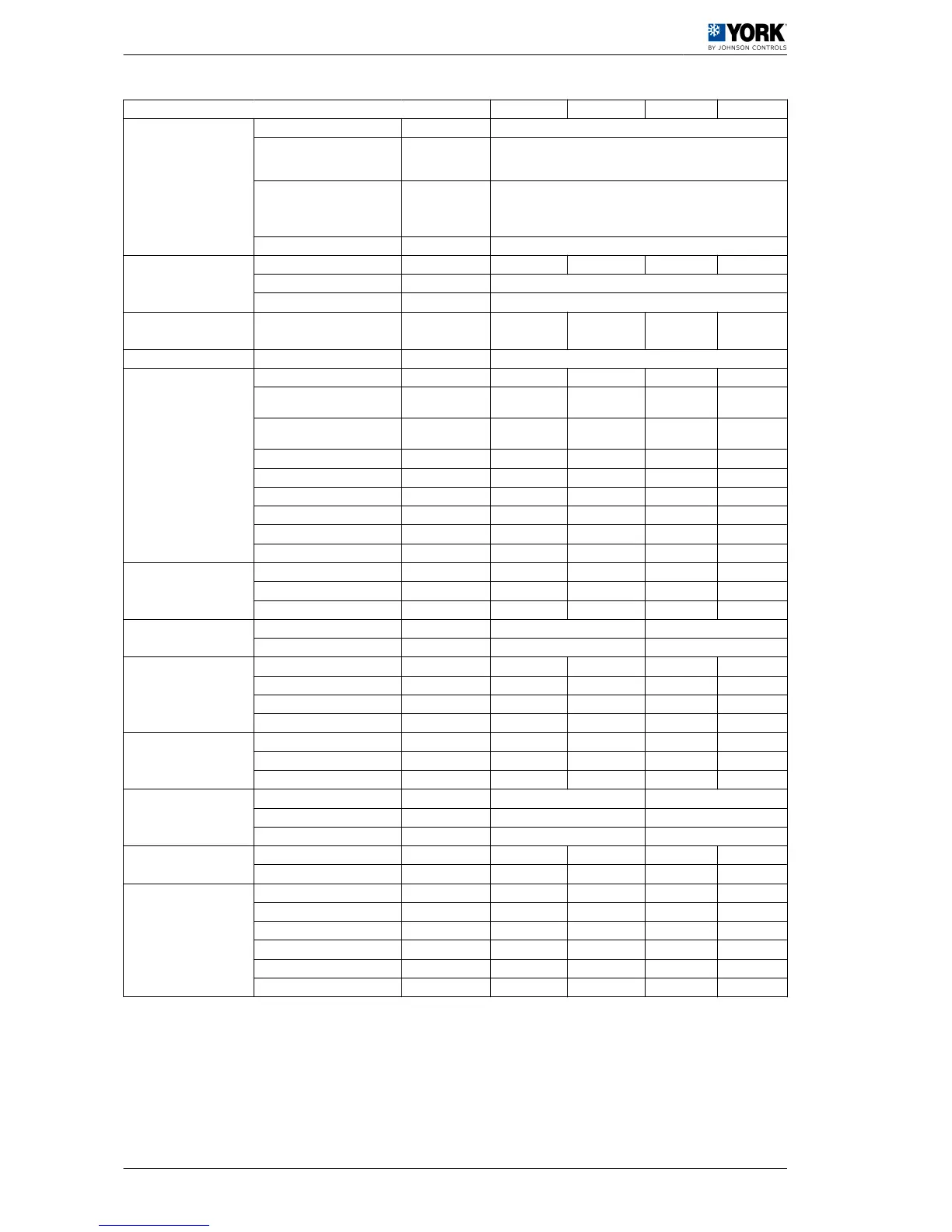
Models ARH/ARD 045 060 075 090
Net (2) kW 90
100% gas consumption (2ND-
H natural gas, G20 at 20 mbar
and 15ºC) (standard)
m
3
/h 8,6
100% gas consumption (2ND-
H natural gas, G20 at 20 mbar
and 15ºC) high capacity (op‐
tional)
m
3
/h 9,8
Stages No. 2
Compressors
Rated/start-up current A 2x12/95 2x15/118 2x20/140 2x25/198
Type and quantity SCROLL, 1 (TANDEM 50 % + 50 %)
Degree of protection IP21
Refrigerant
(R-410A)
kg 14,5 19 20,5 29
Electric power supply V / ph / Hz 400/3+N/50
Indoor fan (3)
Rated air flow m
3
/h 8500 11500 13500 16000
Maximum static pressure with
rated flow (standard drive)
Pa 168 242 240 368
Maximum static pressure with
rated flow (optional HPD drive)
Pa 335 402 >500 >500
Maximum flow m
3
/h 10000 13500 16000 18000
Minimum flow m
3
/h 7000 9500 11500 13000
IP55 Motor (standard) kW 3 4 5,5 7,5
Rated current A 5,5 5,7 7,6 11,7
IP55 Motor (HPD optional) kW 4 5,5 7,5 9,2/11
Rated current A 5,7 7,6 11,7 14/17,4
Indoor coil (evaporator)
Number of elements No. 3 4 3 4
Distance between fins mm 2,11 2,11 1,81 1,81
Front surface m
2
1,44 1,58 1,95 1,06 (x 2)
Air filters (G4)
Quantity per unit No. 6 6
Dimensions mm 470x550x48 565x594x48
Outdoor fan
Diameter / number mm 800/1 800/2 800/2 800/2
Total rated flow m
3
/h 15000 23000 27000 27000
Motor (IP54) kW 1,9 1,9 1,9 1,9
Rated current A 3,5 2x3,5 2x3,5 2x3,5
Outdoor coil (condenser)
Number of elements No. 3 4 2 3
Distance between fins mm 2,11 2,54 1,81 1,81
Front area m
2
2,27 2,49 2.31 (x2) 2.31 (x2)
Net dimensions (4)
Height mm 1316 1367
Length mm 3180 3495
Width mm 2337 2337
Net weight (basic unit with‐
out accessories) (4)
ARH kg 930 985 1145 1220
ARD kg 1040 1095 1255 1330
Electrical features of the
unit
Total rated power kW 17 22 28 36
Total rated current A 32 42 54 70
Total maximum power kW 23 31 38 45
Total maximum current A 42 56 70 83
Circuit breaker (K Curve (5) A 50 63 80 100
Minimum cable section (6) mm
2
10 16 25 35
(1) Data comply with Eurovent conditions, summer: indoor 27 °C TS / 19 °C TH - outdoor TS 35 °C. Winter: Indoor TS 20 °C, outdoor TS 7 °C / TH 6 °C (TS Dry-bulb
thermometer; TH Wet-bulb thermometer).
(2) Add the inside motor consumption to find the total calorific capacity.
(3) See
Indoor fan
, see on page 18
(4) Consider the additional weight of options and accessories. To do so, see
Weight options and accessories
, see on page 7
.
LHV: Lower heating value.
(5) and (6) Circuit breaker with K curve, according to DIN, VDE 0660-104. Section of cables for the power supply line based on copper conductors, 105 ºC. The indicated
circuit breaker and the section of power supply cables are guidelines. They should be adjusted based on the requirements of each installation, distance between units, fall
in planned voltage and on the application of the current regulations with respect to the country where the unit is being installed.
1 Installation manual
1.4 Technical data
6
 Loading...