COOLING CAPACITIES
1
Temperature
Air on
Indoor Coil,
°
F
Temperature of Outdoor Air,
°
F DB
75 95 115 75 95 115
DB WB
To t a l
Cap
MBH
Sens.
Cap
MBH
Power
Input
KW
3
To ta l
Cap
MBH
Sens.
Cap
MBH
Power
Input
KW
3
To t al
Cap
MBH
Sens.
Cap
MBH
Power
Input
KW
3
To t al
Cap
MBH
Sens.
Cap
MBH
Power
Input
KW
3
To t al
Cap
MBH
Sens.
Cap
MBH
Power
Input
KW
3
To t al
Cap
MBH
Sens.
Cap
MBH
Power
Input
KW
3
E2FB090/F3EH090 @ 3300 Supply Air CFM
2
- 60 HZ E1FB120/F3EH120 @ 4000 Supply Air CFM
2
- 60 HZ
92
72 114.5
90.6
7.67 103.4
86.5
9.48 90.8
83.1
10.80 147.5
122.1
11.19 137.0
116.1
12.51 116.4
105.4
13.85
88 81.1 77.4 74.2 107.8 101.8 91.1
84 71.6 68.4 65.2 93.5 87.5 76.8
80 62.1 59.3 56.3 79.2 73.2 62.5
84
67 104.6
81.7
7.08 94.4
80.8
8.90 83.4
78.2
10.25 136.8
110.0
10.70 127.0
104.7
11.96 107.9
98.9
13.25
80 71.2 69.6 66.2 95.7 90.4 84.6
76 60.7 58.4 54.2 81.4 76.1 70.3
72 50.1 47.1 42.3 67.1 61.8 56.0
80
62 94.8
83.5
6.50 85.4
80.1
8.32 75.9
72.8
9.70 122.4
115.0
10.36 113.6
109.4
11.58 96.5
96.5
12.83
76 73.7 69.9 63.3 100.7 95.1 89.0
72 63.9 59.7 53.8 86.4 80.8 74.7
68 54.0 49.5 44.3 72.1 66.5 60.4
72
57 85.0
79.5
5.91 76.4
74.2
7.74 68.5
67.5
9.16 109.4
104.2
9.95 101.6
99.1
11.12 86.3
86.3
12.32
68 68.0 63.2 57.1 89.9 84.9 79.4
64 56.6 52.3 46.8 75.6 70.6 65.1
60 45.1 41.3 36.4 61.3 56.3 50.8
E2FB090/F3EH090 @ 3000 Supply Air CFM
2
- 50 HZ
E1FB120/F3EH120 @ 4000 Supply Air CFM
2
- 50 HZ
92
72 99.6
83.4
6.37 90.0
79.6
7.87 79.0
76.5
8.96 128.3
112.3
9.29 119.2
106.8
10.38 101.3
97.0
11.50
88 74.6 71.2 68.3 99.2 93.7 83.8
84 65.9 62.9 60.0 86.0 80.5 70.7
80 57.1 54.6 51.8 72.9 67.3 57.5
84
67 91.0
75.2
5.88 82.1
74.3
7.39 72.6
71.9
8.51 119.0
101.2
8.88 110.5
96.3
9.93 93.9
91.0
11.00
80 65.5 64.0 60.9 88.0 83.2 77.8
76 55.8 53.7 49.9 74.9 70.0 64.7
72 46.1 43.3 38.9 61.7 56.9 51.5
80
62 82.5
76.8
5.40 74.3
73.7
6.91 66.0
66.0
8.05 106.5
105.8
8.60 98.8
98.8
9.61 84.0
84.0
10.65
76 67.8 64.3 58.2 92.6 87.5 81.9
72 58.8 54.9 49.5 79.5 74.3 68.7
68 49.7 45.5 40.8 66.3 61.2 55.6
72
57 74.0
73.1
4.91 66.5
66.5
6.42 59.6
59.6
7.60 95.2
95.2
8.26 88.4
88.4
9.23 75.1
75.1
10.23
68 62.6 58.1 52.5 82.7 78.1 73.0
64 52.1 48.1 43.1 69.6 65.0 59.9
60 41.5 38.0 33.5 56.4 51.8 46.7
% Nominal Supply Air CFM 80 90 100 110 120
Total Capacity Correction Factor 0.963 0.981 1.000 1.015 1.030
Sensible Capacity Correction Factor 0.935 0.965 1.000 1.049 1.098
Kilowatt Correction Factor 0.981 0.992 1.000 1.008 1.019
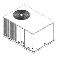
Outdoor Unit Size 7-1/2 Ton 10 Ton
Outdoor Fan Motor KW - 60 HZ 0.83 1.06
Outdoor Fan Motor KW - 50 HZ 0.69 0.88
Blower motor KW is not included. Refer to the SUPPLY AIR BLOWER PERFORMANCE table for the KW rating of the supply air blower motor at the design conditions and add this power
requirement to the KW rating.
1Capacities shown are gross ratings. For net capacities, determine the KW requirement of the supply air blower motor per the SUPPLY AIR BLOWER PERFORMANCE table on page 6.
Convert KW to MBH by the following equation and deduct this equivalent heat from the gross cooling ratings.
Blower Motor Heat (MBH) = Blower Motor KW x 3.415
2Apply the following correction factors to determine the unit performance at different CFM.
3These ratings include the compressor KW and the following KW for the outdoor fan motor(s).
NOTE: Sensible capacity can never exceed total capacity. A higher
corrected sensible capacity indicates a dry coil, and it should
be reduced to the corrected total capacity.
515.41-TG1Y
4 Unitary Products Group