102777-YIM-E-0206
10 Unitary Products Group
TABLE 3: GAS APPLICATION DATA
INPUT CAPACITY (MBH)
AVAILABLE
ON
MODELS
GAS
RATE
1
(FT.3/HR.)
TEMP. RISE °F
AT FULL INPUT
2
3
0 TO 2,000 FEET ABOVE
SEA LEVEL
3,000 FEET ABOVE
SEA LEVEL
4
4,000 FEET ABOVE
SEA LEVEL
4
MAX. MIN. MAX. MIN. MAX. MIN. MIN. MAX.
233 233 205 205 196 196
Y22, Y23,
Y24
217 5 35
466 233 410 205 392 196
Y22, Y23,
Y24
434 15 45
699
5
233 615 205 587 196 Y24 650 20 50
1.
Based on maximum input and 1075 Btu/Ft.
3
2.
The air flow must be adjusted to obtain a temperature rise within the range shown.
3.
On VAV units, individual room damper boxes must go full open in heating mode to ensure airflow falls within temperature rise
range.
4.
For operation at elevations above 2,000 feet and, in the absence of specific recommendations from local authority having jurisdic-
tion, equipment ratings shall be reduced at the rate of 4% for each 1,000 feet above sea level.
5.
Minimum heating CFM for 699 MBH input heat is 11,700 CFM.
If a unit is to be installed on a roof curb other than
a YORK roof curb, gasketing must be applied to all
surfaces that come in contact with the unit under-
side.
If a unit is to be installed on an angle iron frame it
is recommended that it be sized to allow the bot-
tom rail to overhang to facilitate installation of con-
densate drains (see Fig. 4).
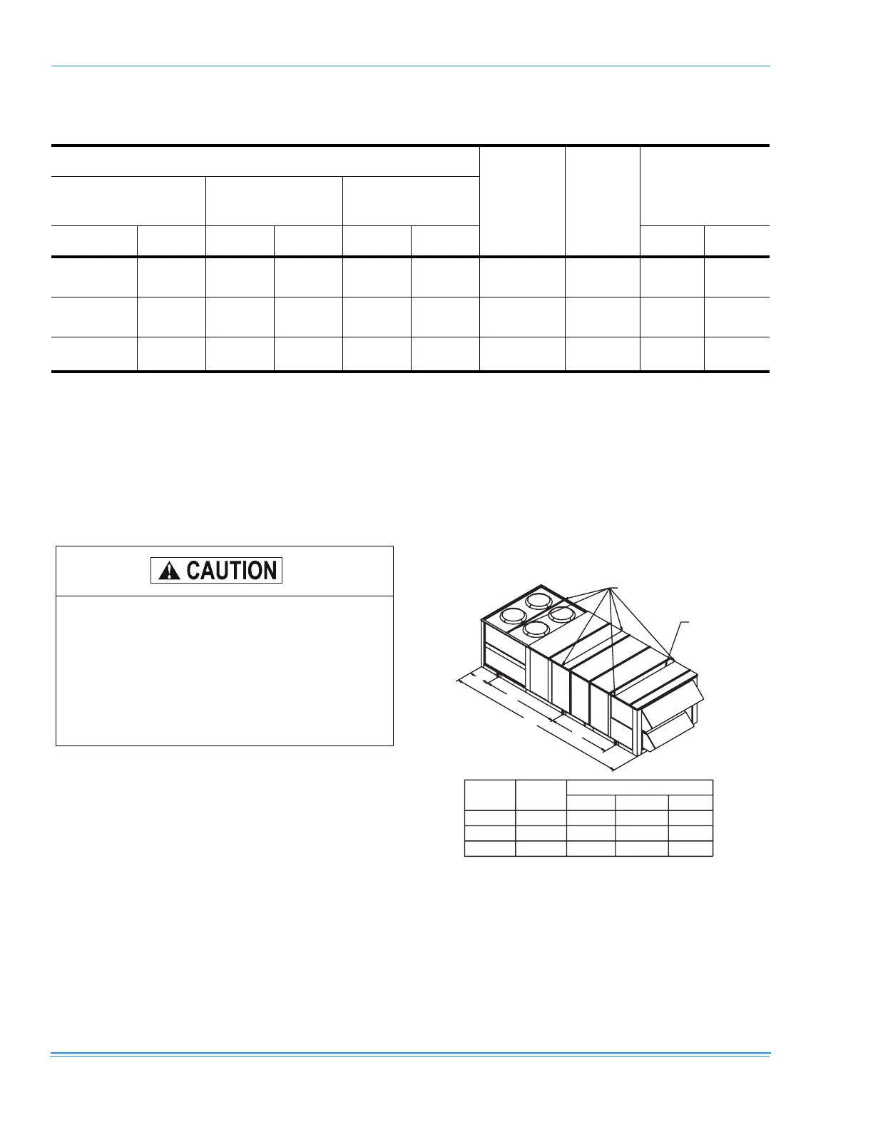
FIGURE 2 - TYPICAL RIGGING
CABLES
SPREADER BARS
(3 PLACES)
20"
A
B
C
UNIT
UNIT
WEIGHT
(LB)
LIFTING LUG DIMENSIONS
A
BC
25 TON
30 TON
40 TON
SEE NOTE 5
SEE NOTE 5
SEE NOTE 5
8' 4"
8' 4"
8' 4"
6' 9"
6' 9"
6' 9"
2' 3"
2' 3"
2' 3"
RIGGING:
1) RIG WITH 6 CABLES, THREE SPREADER BARS - 95" ACROSS WIDTH AND
SPREADER BARS OF LENGTH EQUAL TO "A + B".
2) CENTER OF GRAVITY INCLUDES ECONOMIZER, POWER EXHAUST AND
INLET GUIDE VANES.
3) CAUTION: ALL PANELS MUST BE SECURED IN PLACE WHEN THE UNIT
IS LIFTED.
4) CAUTION: THE CONDENSER COIL SHOULD BE PROTECTED FROM DAMAGE BY
THE RIGGING CABLES WITH PLYWOOD OR OTHER SUITABLE MATERIALS.
5) REFER TO INSTALLATION INSTRUCTIONS.
NOTICE TO RIGGERS
 Loading...