102777-YIM-E-0206
Unitary Products Group 11
NOTE: If the Millennium is VAV with ERV, add the
weight of an exhaust VFD - it will be in the unit.
.
TABLE 4: UNIT WEIGHTS
COMPONENT 25 TON 30 TON 40 TON
Basic Unit 4350 4550 4950
Gas Heat
233 MBH 180 180 180
466 MBH 320 320 320
700 MBH - - 450
Electric Heat
40KW 404040
80KW 105 105 105
108KW 110 110 110
Hot Water Heat
1 Row Coil 70 70 70
2 Row Coil 85 85 85
Steam Heat
1 Row Coil 85 85 85
Blower
Forward Curve Fan (Std Fan) 0 0 0
FC IGV 155 155 175
Air Foil Fan 135 135 155
AF IGV 155 155 180
Motor - Supply Fan
7.5hp 110 - -
10hp 145 145 145
15hp 200 200 200
20hp 240 240 240
25hp - 300 300
Supply Fan Motor VFD See Table 5
Refrigeration
Hi Cap. Evap. Coil - 50 15
T-Coat Evap. 32 30 40
T-Coat cond. 32 30 40
Hot Gas Bypass 10 10 10
Low Ambient Head Pressure Control
208-230/380/460 5 5 5
575 252525
Filters
6" Rigid 70 70 70
Exhaust
1
1.
If ERV and Supply Fan VAV are selected, add the
weight of an Exhaust VFD, Table 5.
Exhaust Type
Barometric 45 65 65
Modulated 140 275 275
Exhaust Motor
5hp 808080
7.5hp 110 110 110
10hp 145 145 145
15hp 200 200 200
Exhaust Motor VFD See Table 6
Economizer
Std. Econ. 235 235 235
Econ. w/ERV 50 50 50
Control
Disconnect 15 15 15
110V outlet 55 55 55
Optilogic 202020
Roof Curb
Partial Curb 415 415 415
Full Curb 615 615 615
TABLE 5: SUPPLY FAN MOTOR VFD WEIGHTS
Supply Fan Motor VFD 230V 460V 575V
W/O Bypass
7.5hp 60 25 30
10hp 60 25 30
15hp 75 50 60
20hp 75 50 60
25hp 115 50 60
W/Bypass
7.5hp 155 90 120
10hp 155 90 120
15hp 185 140 155
20hp 185 140 155
25hp 255 140 155
TABLE 6: EXHAUST FAN MOTOR VFD WEIGHTS
Exhaust Fan Motor 230V 460V 575V
W/O Bypass
5hp 15 10 20
7.5hp 50 15 20
10hp 50 15 20
15hp 65 40 50
25hp 255 140 155
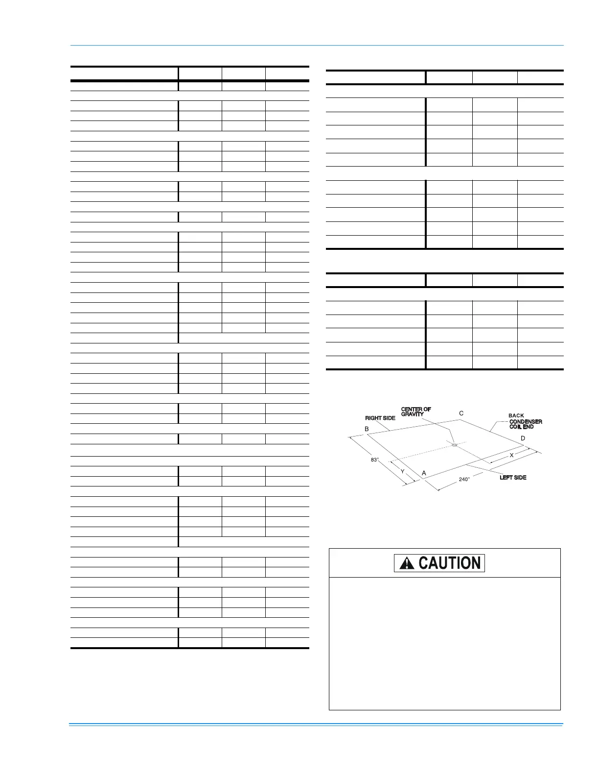
FIGURE 3 - CENTER OF GRAVITY
1
1.
Refer to Tables 7 and 8 for A, B, C, D and X and Y data
respectively.
All panels must be secured in place when the unit is
lifted.
The condenser coils should be protected from dam-
age by the rigging cables with plywood or other suit-
able material.
An adhesive backed cover is provided over the out-
side of the combustion air inlet opening on gas fired
units to prevent moisture from entering the unit
which could cause damage to electrical compo-
nents. Allow this closure label to remain in place
until the combustion air hood is to be installed (Refer
to Figures 7, 8, & 9).
RIGHT SIDE
CENTEROF
GRAVITY
CONDENSER
COILEND
LEFT SIDE
X
Y
83"
240"
A
B
C
D
BACK
 Loading...