Optional gas heat
The optional gas-fired heaters have aluminized-steel
or optional stainless steel, tubular heat exchangers
with spark ignition with proven pilot.
This unit is shipped from the factory for use with
natural gas at elevations up to 2000 ft (610 m) above
sea level. The unit may be field-converted for use
with propane gas and/or elevations above 2000 ft
with a listed conversion kit.
Note: Installation of this furnace at altitudes
above 2000 ft (610 m) shall be in accordance
with local codes, or in the absence of local
codes, the National Fuel Gas Code, ANSI
Z223.1/NFPA 54 or National Standard of
Canada, Natural Gas and Propane Installation
Code, CSA B149.1.
Table 48: Gas application data
Unit
Size (tons) Heat size
Input (MBH) Output (MBH)
Temp. rise (°F)
1
YV28 (N,S)1 400 324 25-35
(N,S)3 620 506 35-60
YV30 (N,S)1 400 324 20-35
(N,S)3 620 506 35-55
YV35 (N,S)1 400 324 20-30
(N,S)3 800 648 35-60
YV40 (N,S)1 400 324 15-25
(N,S)3 800 648 35-50
YV50 (N,S)1 400 324 15-20
(N,S)3 800 648 30-40
1 On VAV units with a non-modulating furnace, individual VAV
boxes must be fully open in heating mode to ensure airflow
falls within the temperature rise range.
Table 49: Gas heat allowable air flow
Supply air (CFM) Heating
Model Heat size
Min Max
(N,S)1 8250 12375
YV28
(N,S)3 8250 12375
(N,S)1 9000 13500
YV30
(N,S)3 9000 13500
(N,S)1 10500 15750
YV35
(N,S)3 10500 15750
(N,S)1 12000 18000
YV40
(N,S)3 12000 18000
(N,S)1 15000 20000
YV50
(N,S)3 15000 20000
Gas piping
Proper sizing of gas piping depends on the cubic
feet per hour of gas flow required, specific gravity of
the gas, and the length of run.
Follow the “National Fuel Gas Code” Z223.1 (in
U.S.A.) or the current Gas Installation Codes
CSA-B149.1 (in Canada) in all cases unless they
are superseded by local codes or gas utility
requirements.
See Table 50. The heating value of the gas may vary
by locality. You must check the value with the local
gas utility.
Note: There may be a local gas utility
requirement specifying a minimum diameter
for gas piping. All units require a 1 1/4-in.
pipe connection at the entrance fitting. The
supply line should not be sized smaller than the
entrance fitting size.
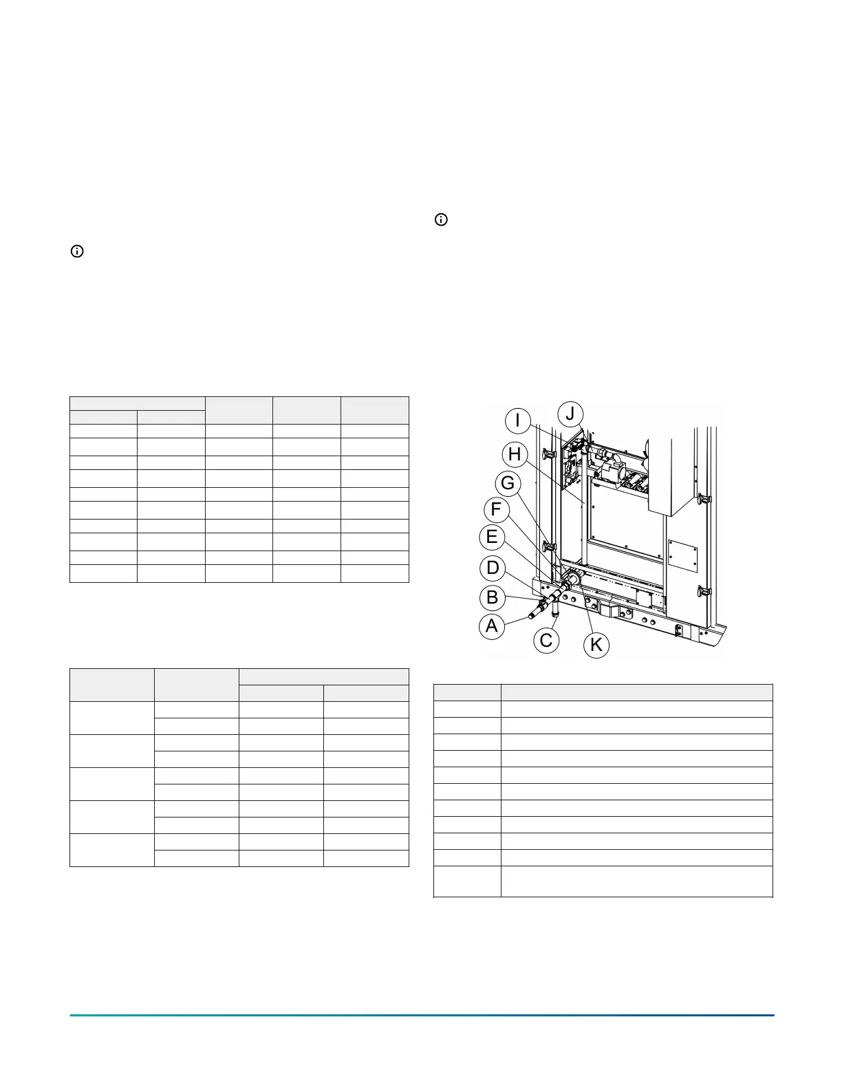
The following figures show the gas piping.
Figure 56: Low heat gas unit with side gas
connection arrangement
Item Description
A Extended pipe
B Manual shut-off valve
C Sediment trap
D 4 1/2-in. long nipple
E 4-in. long nipple
F Union
G 7-in. long nipple
H 28-in. pipe
I 90° elbow
J 3.7-in. long nipple
K
Caulk between pipe and base rail grommet to
provide watertight seal
Installation Manual: YORK
®
Sun
™
Select YV28 to YV50
66
Johnson Controls Ducted Systems