Item Description
A High tube
B Low tube
7. Determine the length of tubing required to
run from the DPS down through the hole in
the knock-out in the bottom of the control
box, and to the required location for obtaining
the supply-air duct pressure.
8. Connect the field-supplied tubing to the High
pressure port of the DPS. The Low and High
pressure ports can be identified by the sticker
and embossment on the sensor and are
shown in Figure 31 and Figure 32.
9. Following the same path as the building-
pressure tubing in Step 6, route the tubing
through the control box and down through
the hole in the control box base, as shown in
Figure 33.
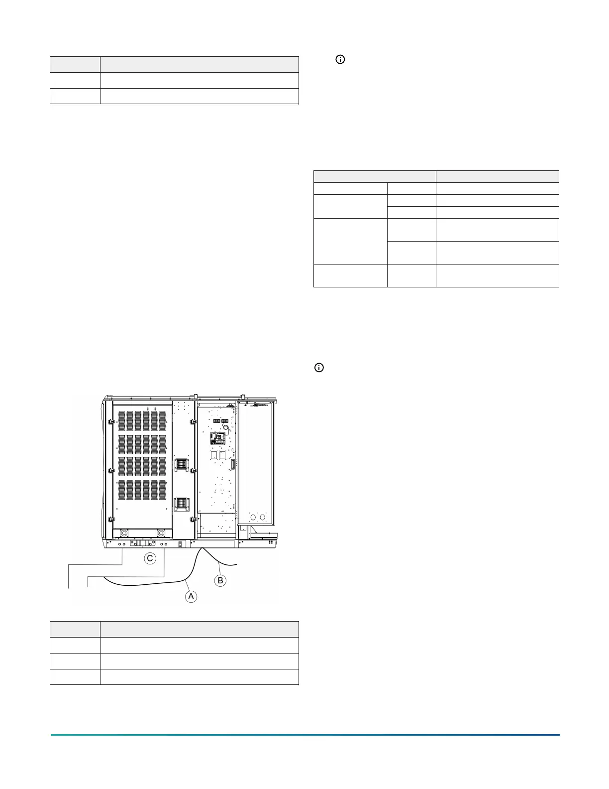
10. After exiting the unit base, route the tubing
to a field-supplied static pressure tap in the
supply duct located at a point where constant
pressure is expected. An example of the full-
tubing routing can be seen in Figure 34.
Figure 34: Routing the tubing
Item Description
A High SA duct pressure
B Low building pressure
C Supply air duct
Note: To prevent an unstable signal due to
air turbulence, make sure that there are no
obstructions, turns, or VAV terminal boxes
upsream or downstream of the sensing
tube location for at least a distance of 6 to
10 times the duct diameter.
Utilities entry
Table 3: Utilities entry
Entry description Opening size diameter (in.)
Control wiring Bottom 1-in. knockout for field drilling
Front Field drilled to maximum of 3 in.
Power wiring
Bottom Field drilled to maximum of 3 in.
Front
11
,
22
2 5/8-in. hole with 1 1/2-in.
grommet
Gas piping
Bottom
33
1/4-in. pilot hole in gas heat
base pan
Condensate drain
Front
2
,
44
2 1/2-in. hole with 1 1/2-in.
grommet
1 1-1/4 in. NPT gas piping is required.
2 You must insert the piping through the factory-installed
grommet for a watertight seal.
3 Factory provided pilot hole shows the hole location to
facilitate the drilling of entry holes.
4 1-in. NPT male connection piping is required.
Note: You must field seal all entry holes to
prevent rainwater entry into the building.
Condensate drain line installation
About this task:
After the unit is installed in the field, the condensate
drain line will need to be connected to the
field supplied drain line. The condensate drain
connection is oriented for a through the side
connection as shown in Figure 35.
Installation Manual: YORK
®
Sun
™
Select YV28 to YV50
24
Johnson Controls Ducted Systems