5. Connect the field-supplied tubing to the Low
pressure port of the DPS. The Low and High
pressure ports can be identified by the sticker
and embossment on the sensor and are
shown in Figure 31 and Figure 32.
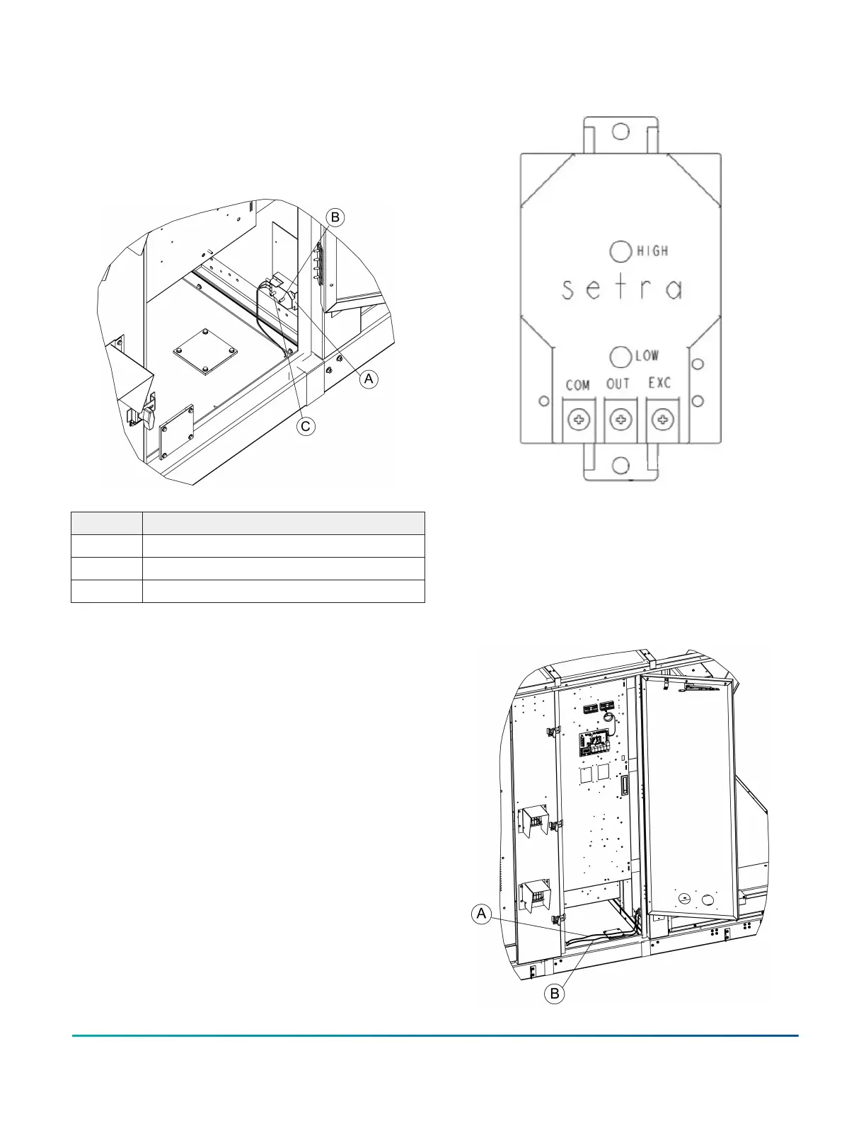
Figure 31: DPS detail
Item Description
A DPS
B High pressure port
C Low Pressure port
Figure 32: DPS port locations
6. Route the tubing through the control box and
down through the hole in the control box base
knock out, as shown in Figure 33. After exiting
the unit base, route the tubing to the desired
location for obtaining a constant building
pressure reading.
Figure 33: Routing the tubing
Installation Manual: YORK
®
Sun
™
Select YV28 to YV50
23
Johnson Controls Ducted Systems