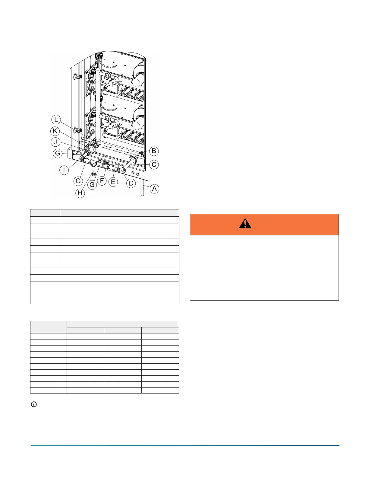
Figure 59: High heat gas unit with bottom gas
connetion arrangement
Item Description
A Extended Pipe
B 90° elbow
C 13.5-in. pipe
D 90° elbow
E 5-in. long nipple
F Manual shut-off valve
G 4-in. long nipple
H Sediment trap
I 90° elbow
J Reducer
K 7-in. long nipple
L 90° elbow
Table 50: Gas pipe sizing - capacity of pipe
Nominal iron pipe size
Length of pipe (ft.)
3/4 in. 1 in. 1 1/4 in.
10 278 520 1050
20 190 350 730
30 152 285 590
40 130 245 500
50 115 215 440
60 105 195 400
70 96 180 370
80 90 170 350
90 84 160 320
100 79 150 305
Note: Maximum capacity of pipe in cubic feet
of gas per hour based upon a pressure drop of
0.3 in. W.C. and 0.6 specific gravity gas.
Gas connection
About this task:
The gas supply line can be routed within the space
and roof curb with the exit through the unit’s
basepan. See Physical dimensions for the gas piping
inlet location. Typical supply piping arrangements
are shown in the Gas piping section. All pipe nipples,
fittings, and the gas cock are field supplied.
Apply the following gas piping recommendations:
• You must install a drip leg or sediment trap
and a ground joint union in the gas piping.
• When required by local codes, install a manual
shut-off valve outside of the unit.
• Use wrought iron or steel pipe for all gas lines.
Apply pipe dope sparingly to male threads
only.
• If local codes allow the use of a flexible gas
appliance connector, always use a new listed
connector. Do not use a connector which has
previously serviced another gas appliance.
WARNING
Natural gas may contain some propane. Propane is
an excellent solvent and will quickly dissolve white
lead and most standard commercial compounds. A
special pipe dope must be used when assembling
wrought iron or steel pipe. Shellac based compounds
such as Gaskolac or Stalastic, and compounds such
as Rectorseal #5, Clydes’s or John Crane may be
used.
• Clean all piping of dirt and scale. Hammer on
the outside of the pipe and blow out loose
particles. Before initial start-up, make sure
that all gas lines external to the unit are
purged of air.
• The gas supply must be a separate line and
installed in accordance with all safety codes as
prescribed under Limitations.
• You must install a 1/8-in. NPT plugged
tapping, accessible for test gage connection,
immediately upstream of the gas supply
connection to the unit.
Installation Manual: YORK
®
Sun
™
Select YV28 to YV50
68
Johnson Controls Ducted Systems