JOHNSON CONTROLS
109
SECTION 3 - OPTIVIEW™ CONTROL CENTER FUNCTIONS AND NAVIGATION
FORM 160.84-OM1
ISSUE DATE: 9/21/2017
3
MESSAGE DESCRIPTION
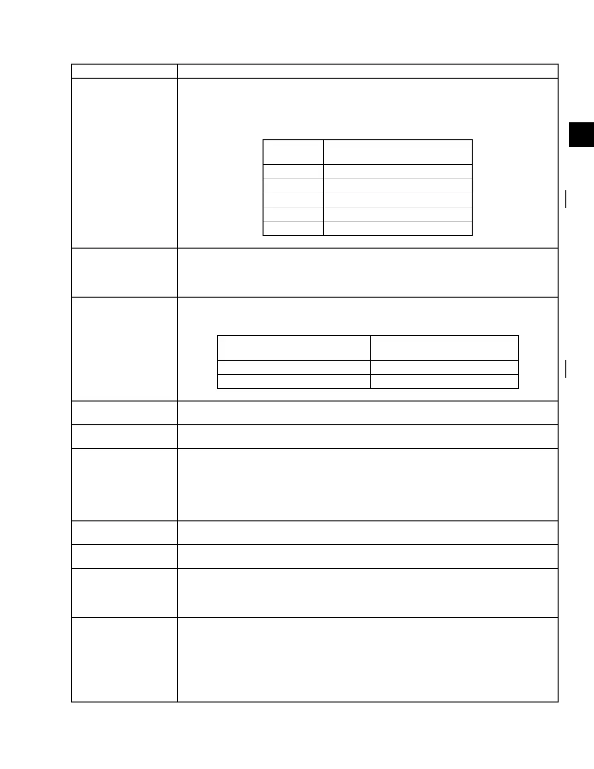
VSD – 105% MOTOR
CURRENT OVERLOAD
The 105% motor current overload value is based on the highest output current compared to the
programmed Motor Current value displayed on the Control panel. The 105% motor current over-
load value is 1.05 times the programmed Motor Current value displayed on the Control panel.
The motor current overload value must be greater than the shutdown value for 40 continuous
seconds for this shutdown to occur.
DRIVE
MODEL
MAXIMUM MOTOR CURRENT
OVERLOAD SHUTDOWN VALUE
0490, 0490A 490 Amps
0612A 612 Amps
0730A 730 Amps
0774 774 Amps
1278A 1278 Amps
When the condition clears, the chiller can be started after the CLEAR FAULTS key is pressed.
VSD – MOTOR
CURRENT THD FAULT
This shutdown provides protection to the compressor motor. High levels of current total harmon-
ic distortion (THD) can cause the motor to overheat. Verify that all wiring is properly connected
between the inverter and the output harmonic lter. When the condition clears, the chiller can be
started after the CLEAR FAULTS key is pressed.
VSD – PHASE A INPUT
DCCT
The input current in each phase to the VSD is measured during the precharge time. If the input
current does not exceed the shutdown value for the given model of drive listed below, then this
shutdown is generated.
DRIVE
MODEL
MINIMUM INPUT CURRENT
SHUTDOWN VALUE
0490A, 0490, 0612A, 0730A, 1278A 5.0 amps
0774 15.0 amps
When the condition clears, the chiller can be started after the CLEAR FAULTS key is pressed.
VSD – PHASE B INPUT
DCCT
See “VSD –PHASE A INPUT DCCT” message preceding.
VSD – PHASE C INPUT
DCCT
See “VSD – PHASE A INPUT DCCT” message preceding.
VSD – PHASE A MO-
TOR DCCT
The motor current in each phase of the VSD is measured at the beginning of the run command.
The motor current at this time should measure very low. This low value will be used as the zero
current value for the rest of this run time. The motor current is then monitored for the next 1.5
seconds to ensure that a minimum amount of current is owing to the motor. If at the end of the
1.5 second time a minimum of 25 amps peak is not detected, then this shutdown is generated.
When the condition clears, the chiller can be started after the CLEAR FAULTS key is pressed.
VSD – PHASE B MO-
TOR DCCT
See “VSD –PHASE A MOTOR DCCT” message preceding.
VSD – PHASE C MO-
TOR DCCT
See “VSD – PHASE A MOTOR DCCT” message preceding.
VSD – PHASE LOCKED
LOOP
The VSD must be able to determine the input voltage frequency from the input voltage measure-
ment. If the input voltage frequency is not stable enough for the VSD to make this determination,
then this shutdown is generated. When this condition clears, the chiller can be started after the
CLEAR FAULTS key is pressed.
VSD – PRECHARGE
LOCKOUT
If the unit fails to complete pre-charge (due to VSD – PRECHARGE – LOW DC BUS VOLTAGE
or VSD – PRECHARGE – HIGH DC BUS VOLTAGE), the VSD shall time 10 seconds before
clearing the fault and allowing another pre-charge to start. The unit’s fan(s) and water pump(s)
shall remain energized during this time. The VSD shall allow up to three consecutive pre-charge-
related faults to occur. After the third consecutive pre-charge-related fault, this shutdown is
generated. When the condition clears, the chiller can be started after the CLEAR FAULTS key is
pressed.
TABLE 12 - SAFETY SHUTDOWN MESSAGES (CONT'D)