JOHNSON CONTROLS
137
SECTION 6 - PRINTING
FORM 160.84-OM1
ISSUE DATE: 9/21/2017
6
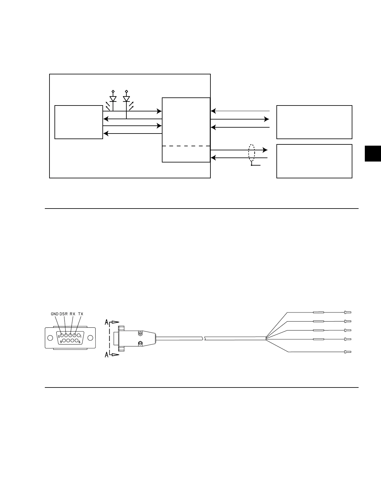
The connector on the PC has male pins; therefore, the
mating cable needs to terminate DB9/F (female pin)
connector.
MICRO
OPTIVIEW
R
TX1
G
RX1
PC
HYPERTERMINAL
EQ 232 Port
SC-EQUIP
COM 1
RS-232
TX
DB9
2
5
4
Port 2B
RX
TX
COM
GND
DSR
GTX
GRX
COM 4B
J2
9
4
2
J2
7
6
FIGURE 51 - COMMUNICATIONS BLOCK DIAGRAM
LD14492A
A serial cable to go from the OptiView Control Pan-
el to the serial port is available from the parts center
(P/N 075-90490-230).
LD17607
VIEW A-A
RED
WHITE
GREEN
DRAIN
FIGURE 52 - OPTIVIEW PANEL TO PC SERIAL CABLE