FORM 155.19-EG3 (1011)
5JOHNSON CONTROLS
Ratings
Computerized Performance Ratings
Each chiller selection is custom-matched to meet the
individual application requirements. It is not practical to
provide tabulated information for all possible combina-
tions. Computerized performance ratings are available
through each Johnson Controls sales ofce.
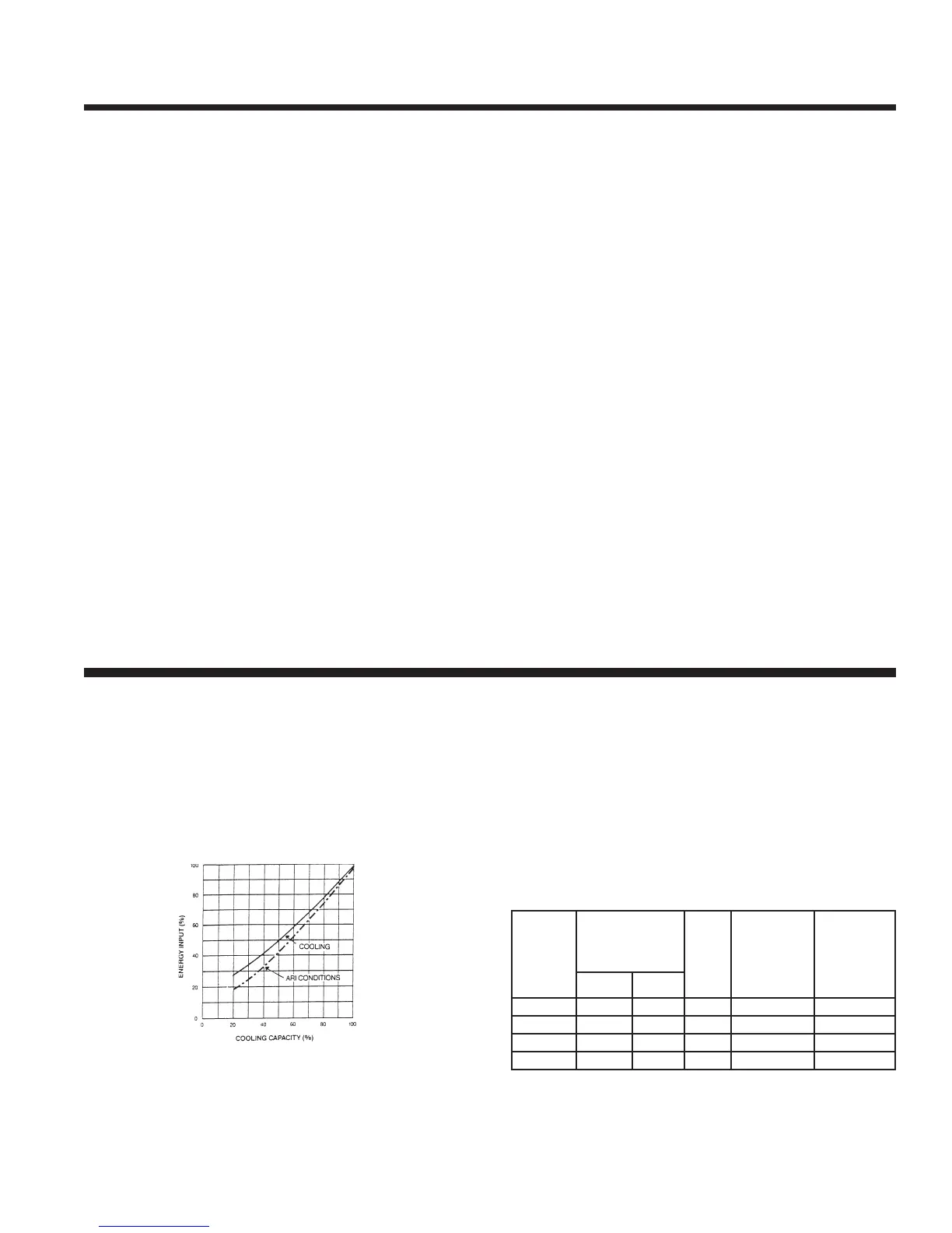
Figure 1 details the high efciency part load performance
of the YPC Absorption Chiller. At both constant tower
water temperatures and ARI adjusted entering tower tem-
peratures, the unique Two-Stage design delivers superior
economy at low loads. Table 1 details the YPC machine’s
superior IPLV according to ARI 560-2000.
FIGURE 1 – ENERGY INPUT VS. OUTPUT
Shows the part load performance of the YPC Chiller. The
highest efciency is achieved between 50 and 100 percent
chilling capacity. Valid for leaving chilled water tempera-
ture 41°F-52°F (5.0°C-11.1°C).
IPLV (expressed as a COP) = 1.38
TABLE 1 - IPLV ANALYSIS
4. Condenser
Refrigerant from two sources – (1) liquid resulting from
the condensing of vapor produced in the First-Stage
Generator and (2) vapor produced by the Second- Stage
Generator enters the Condenser. As the liquid refrigerant
enters the low pressure of the condenser, it ashes to
vapor. The two sources of refrigerant vapor combine and
condense to liquid as they are cooled by the condenser
water. The liquid then ows down to the Evaporator.
5. Evaporator
Refrigerant liquid from the Condenser passes through a
metering valve and ows down to the Refrigerant Pump,
where it is pumped up the the top of the Evaporator. Here
the liquid is sprayed out as a ne mist over the Evapora-
tor tubes. Due to the extreme vacuum (6 mm Hg) in the
Evaporator, some of the refrigerant liquid evaporator,
creating the refrigerant effect. (This vacuum is created by
hygroscopic action-the strong afnity LiBr has for water-in
the Absorber directly below.)
The refrigerant effect cools the returning system chilled
water in the Evaporator tubes. The refrigerant liquid/vapor
picks up the heat of the returning chilled water, cooling it
from 54°F (12.2°C) to 44°F (6.6°C). The chilled water is
then supplied back to the system.
6. Absorber
As the refrigerant liquid/vapor descends to the Absorber
from the Evaporator, a concentrated solution coming
from the Heat Exchanger is sprayed out into the ow of
descending refrigerant. The hygroscopic action between
LiBr and water, and the related changes in concentration
and temperature, result in the creation of an extreme
vacuum in the Evaporator directly above. The dissolving
of the LiBr in water gives off heat, which is removed by
condenser water entering from the cooling tower at 85°F
(29.4°C) and leaving form the Condenser at 92°F (33.3°C).
The resultant dilute LiBr solution collects in the bottom of
the Absorber, where it ows down to the Solution Pump.
The chilling cycle is now completed and begins again at
Step 1.
LOAD (%)
ENTERING CON‑
DENSER WATER
TEMP
COP
WEIGHTING
FACTOR
(FROM ARI
560‑2000)
WEIGHTED
AVERAGE
COP
°F °C
100 85.0 29.44 1.19 0.01 0.012
75 77.5 25.28 1.32 0.42 0.554
50 70.0 21.11 1.46 0.45 0.657
25 70.0 21.11 1.3 0.12 0.156