FORM 155.19-EG3 (1011)
17JOHNSON CONTROLS
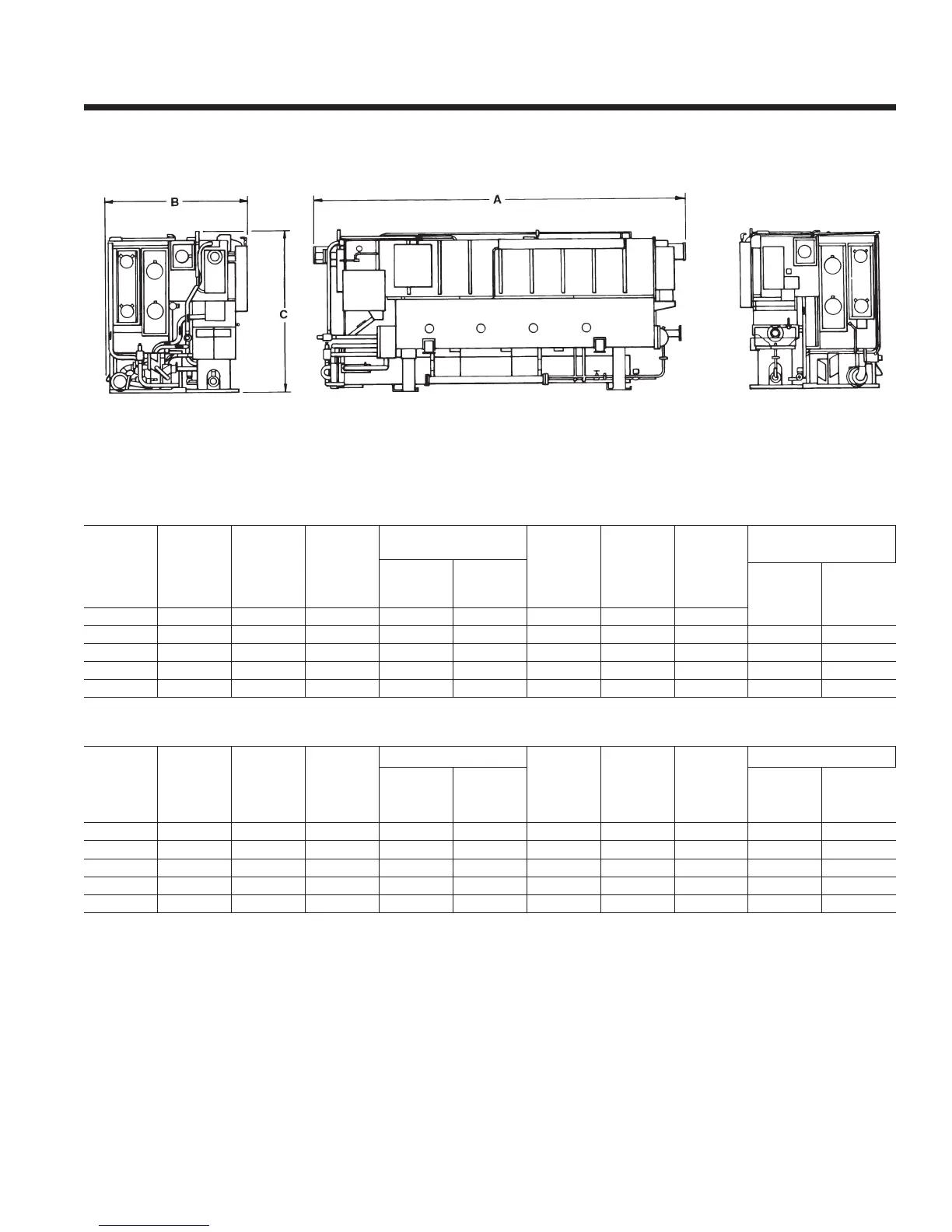
Dimensions
Johnson Controls is committed to a policy of continuous product improvement. Dimensions subject to change
without notice. Consult factory-submitted drawings.
NOTES:
1. Tube pull space for the main shell is equal to the unit length on either end of the machine. rst-stage generator tube pull space is required
on the end opposite the steam inlet.
2. Steam inlet and condensate outlet are 150 PSIG raised face anged.
UNIT TYPE
LENGTH
1
(IN.) A
WIDTH (IN.)
B
HEIGHT
(IN.) C
RIGGING WEIGHT
OPERATING
WEIGHT
(LBS.)
STEAM
2
INLET PIPE
(IN.)
CONDEN‑
SATE
2
OUTLET
PIPE
INSULATION AREAS
LBS. NO
CHARGE
LBS.
SHIPPED W/
CHARGE
INLET PIPE
(IN.)
OUTLET
PIPE (IN.)
14SC 201 74 88 20900 22500 24300 2.5 3/4
16SL 235 89 103 30200 34150 37800 4.0 3/4 172 398
17S 235 89 103 31000 34950 38600 4.0 3/4 172 398
18S 274 90 109 36900 41600 45800 4.0 3/4 205 474
19S 314 90 109 44500 49600 54900 4.0 3/4 237 506
UNIT TYPE
LENGTH
1
(mm) A
WIDTH
(mm) B
HEIGHT
(mm) C
RIGGING WEIGHT
OPERATING
WEIGHT
(kg)
STEAM
2
WEIGHT
(kg)
INLET PIPE
(mm)
CONDEN‑
SATE
2
OUTLET
PIPE (mm)
INSULATION AREAS
kg NO
CHARGE
kg SHIPPED
W/CHARGE
COLD AR‑
EAS (m
2
)
HOT AREAS
(m
2
)
14SC 5106 1880 2236 9480 10206 11022 63.5 19.1 11 24
16SL 5969 2261 2616 13698 15490 17146 101.6 19.1 16 37
17S 5969 2261 2616 14061 15853 17509 101.6 19.1 16 37
18S 6960 2286 2769 16738 18869 20775 101.6 19.1 19 44
19S 7976 2286 2769 20185 22498 24902 101.6 19.1 22 47