JOHNSON CONTROLS
24
FORM 160.81-NOM1
ISSUE DATE: 10/3/2020
SECTION 1 – INSTALLATION
Form 7 Shipment
1. Locate evaporator and condenser shells in their
nal position.
2. Remove shipping closures from the anges on
refrigerant line on bottom of evaporator and con-
denser. (Shells are shipped with a holding charge
of nitrogen.) Discard gaskets. Install orice plate
using new gaskets and 3/4" x 3" long cap screws
and nuts.
3. Bolt tube sheets together using cap screws, lock
washers and nuts. (Refer to Figure 10 on page
24.)
4. Assemble vibration isolators to the unit. (Refer
to Locating and Installing Isolator Pads on page
16.)
5. Level shells in both directions. The longitudi-
nal alignment of the shell should be checked by
placing a level on the top of the shell, next to the
discharge connection. The transverse alignment
should be checked by placing a level on the tops
of both end sheets. After shell is leveled, wedge
and shim each corner of the shell to solidly sup-
port it while assembling the other parts.
6. Lift compressor-motor assembly and remove
packing materials and shipping skids. Keep the
compressor unit supported by the hoist until all
connections are nally made to the shell assem-
bly. (Refer to Figure 8 on page 21 for rigging
method.) Remove closure covers and be sure
anges are clean.
Evaporator-Condenser Shells – Remove all refriger-
ant connection covers.
Shells are shipped with a 5 psig (34 kPa)
nitrogen charge.
7. Place gasket on the evaporator suction ange and
lower the compressor assembly. Guide the studs
through the gasket and suction ange on top of
evaporator. (Refer to Figure 11 on page 26.)
8. Insert the cap screws, washers, and nuts to fasten
the motor to the motor support bracket. Level the
compressor-motor. If necessary, adjust the screws
and nuts to level compressor, and add shims if
necessary, between the motor feet and the sup-
port. (Refer to Figure 11 on page 26.)
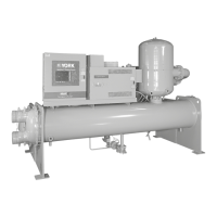
FIGURE 10 - FORM 7 SHIPMENT
LD09035
 Loading...


