JOHNSON CONTROLS
61
SECTION 5 – MAINTENANCE
FORM 160.81-NOM1
ISSUE DATE: 10/3/2020
5
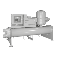
FIGURE 25 - DUAL OIL FILTER ISOLATION VALVE
LD09034
Do not force the valve stem past the stop.
Damage to the Isolation Valve will occur.
FILTER DRIER REPLACEMENT
The filter driers should be changed annually or when
excessive amount of oil is indicated in the refrigerant
charge.
When the filter driers require changing the chiller must
be shut off.
1. Close the service isolation valves identied in
schematic drawing, see Figure 19 on page 47.
2. Carefully remove the insulation on the lter driers
located on the eductor block.
3. Relieve the pressure from the circuit using the
pressure access tting located on the side of the
eductor block. Connect a refrigeration pressure
hose to the pressure access port and drain the oil
and refrigerant into a suitable refrigerant recovery
container.
4. Loosen the Rota-Lock
®
Nuts at each end of the
lter driers. Remove the lter driers.
5. Teon
®
seal washers are used to seal the lter dri-
er connections. These washers must be replaced
when the lter driers are replaced.
6. Tighten the Rota-Lock
®
Nuts at each end of the
three lter driers to a torque of 60 ft.-lb. (81 N·m)
7. Evacuate the air from the oil lter to 500 microns
PSIG.
8. Open the ve hand isolation valves. The chiller is
now ready to be placed back into service.
The YORK control panel will automatically display
the message “DIRTY OIL FILTER” when the differ-
ential pressure reaches 15 PSID across the oil filter. A
safety shutdown will be initiated if the oil pressure dif-
ferential pressure reaches 25 PSID. The control panel
will display the message “CLOGGED OIL FILTER”
OIL FILTER REPLACEMENT
Single Oil Filter
The chiller must be OFF. Turn the rocker switch to the
OFF position; turn the circuit breaker to the off position
to prevent the chiller from being accidentally started.
1. Close the hand isolation valves on the inlet and
outlet oil lines going to and from the oil lter.
2. Relieve the refrigerant pressure and oil in the oil
lter and the oil lines through the pressure access
port tting, located on the top of the lter housing.
Connect a refrigeration pressure hose to the pres-
sure access port and drain the oil and refrigerant
into a suitable refrigerant recovery container.
3. Position a container to collect the oil (less than 2
quarts, 1.9 liters). Loosen and remove the drain
nut at the bottom of the oil lter housing; drain the
oil into the container.
4. Unscrew the oil lter bowl locking nut.
5. Remove the oil lter element.
6. Install a new element.
7. Install a new O-ring on the top of the oil lter
bowl.
8. Tighten the oil lter bowl locking nut.
9. Open the hand isolation valves.
10. The chiller is ready to be restarted.
Dual Oil Filters (Optional)
The dual oil filter option allows one oil filter to be iso-
lated and changed with the chiller in operation.
1. Isolate the left hand lter by turning the valve
stem parallel with the valve body 90º counter
clockwise. Refer to Figure 25 on page 61.
2. Isolate the right hand lter by turning the valve
stem 1/4 turn clockwise.
 Loading...


