JOHNSON CONTROLS
84
SECTION 5 - TECHNICAL DATA
Form 201.47-ICOM1
Issue date: 17/11/2022
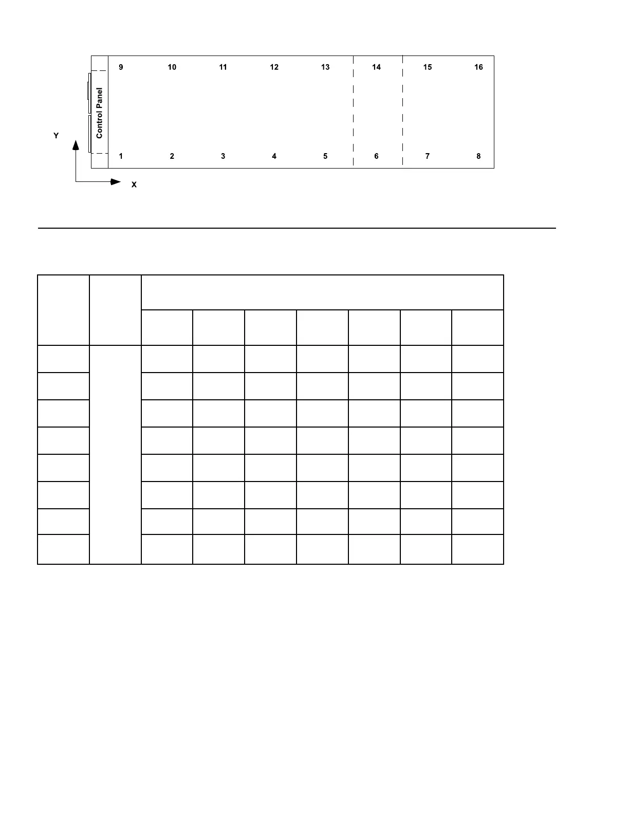
Table 10 - Isolator selection and mounting locations (cont'd)
Location
Isolator
Y-Dimen-
sion (All
YVAA
Models),
in. (mm)
Isolator X-Dimension listed by YVAA Model Designation, in. (mm)
0294/1034 0324/1134 0331/1161 0306/1076 0309/1089 0334/1174 0491/1731
1
1.7
(43)
9.5
(242)
9.5
(242)
9.5
(242)
9.5
(242)
9.5
(242)
9.5
(242)
9.5
(242)
2 82.3
(2091)
82.3
(2091)
82.3
(2091)
82.3
(2091)
82.3
(2091)
82.3
(2091)
82.3
(2091)
3 142.6
(3622)
142.6
(3622)
142.6
(3622)
142.6
(3622)
142.6
(3622)
142.6
(3622)
142.6
(3622)
4 219.7
(5581)
219.7
(5581)
219.7
(5581)
219.7
(5581)
219.7
(5581)
219.7
(5581)
219.7
(5581)
5 335.6
(8524)
335.6
(8524)
299.7
(7612)
299.7
(7612)
299.7
(7612)
299.7
(7612)
300.1
(7621)
6 409.1
(10,392)
409.1
(10,392)
421.8
(10,712)
421.8
(10,712)
422.1
(10,721)
7
8
Notes:
1. Contact your nearest Johnson Controls Sales Oce for weight data.
2. All isolator mounting holes are 19 mm.
3. Dimensions are in inches (mm).
LD18587
Figure 34 - Isolator selection and mounting locations