SECTION 5 - TECHNICAL DATA
JOHNSON CONTROLS
83
Form 201.47-ICOM1
Issue date: 17/11/2022
5
LD18587
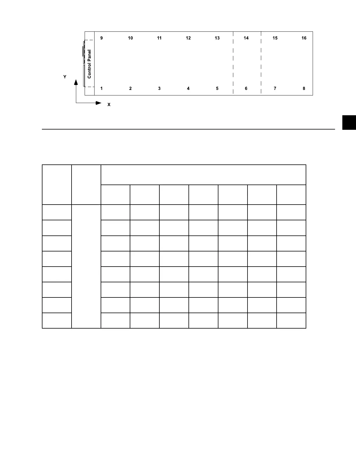
Table 10 - Isolator selection and mounting locations (cont'd)
Location
Isolator
Y-Dimen-
sion (All
YVAA
Models),
in. (mm)
Isolator X-Dimension listed by YVAA Model Designation, in. (mm)
0259/0919 0266/0936 0219/0769 0229/0809 0264/0924 0269/0949 0246/0866
9
86.7
(2202)
9.4
(239)
9.4
(239)
9.5
(242)
9.5
(242)
9.5
(242)
9.5
(242)
9.5
(242)
10 82.2
(2089)
82.2
(2089)
82.3
(2091)
82.3
(2091)
82.3
(2091)
82.3
(2091)
82.3
(2091)
11 142.5
(3619)
142.5
(3619)
137.1
(3483)
142.6
(3622)
142.6
(3622)
142.6
(3622)
142.6
(3622)
12 219.6
(5579)
219.6
(5579)
219.7
(5581)
219.7
(5581)
219.7
(5581)
219.7
(5581)
219.7
(5581)
13 291.1
(7395)
291.1
(7395)
335.2
(8515)
335.2
(8515)
335.2
(8515)
335.2
(8515)
335.2
(8515)
14
15
16
Notes:
1. Contact your nearest Johnson Controls Sales Oce for weight data.
2. All isolator mounting holes are 19 mm.
3. Dimensions are in inches (mm).
Figure 33 - Isolator selection and mounting locations