JOHNSON CONTROLS
86
SECTION 5 - TECHNICAL DATA
Form 201.47-ICOM1
Issue date: 17/11/2022
LD18587
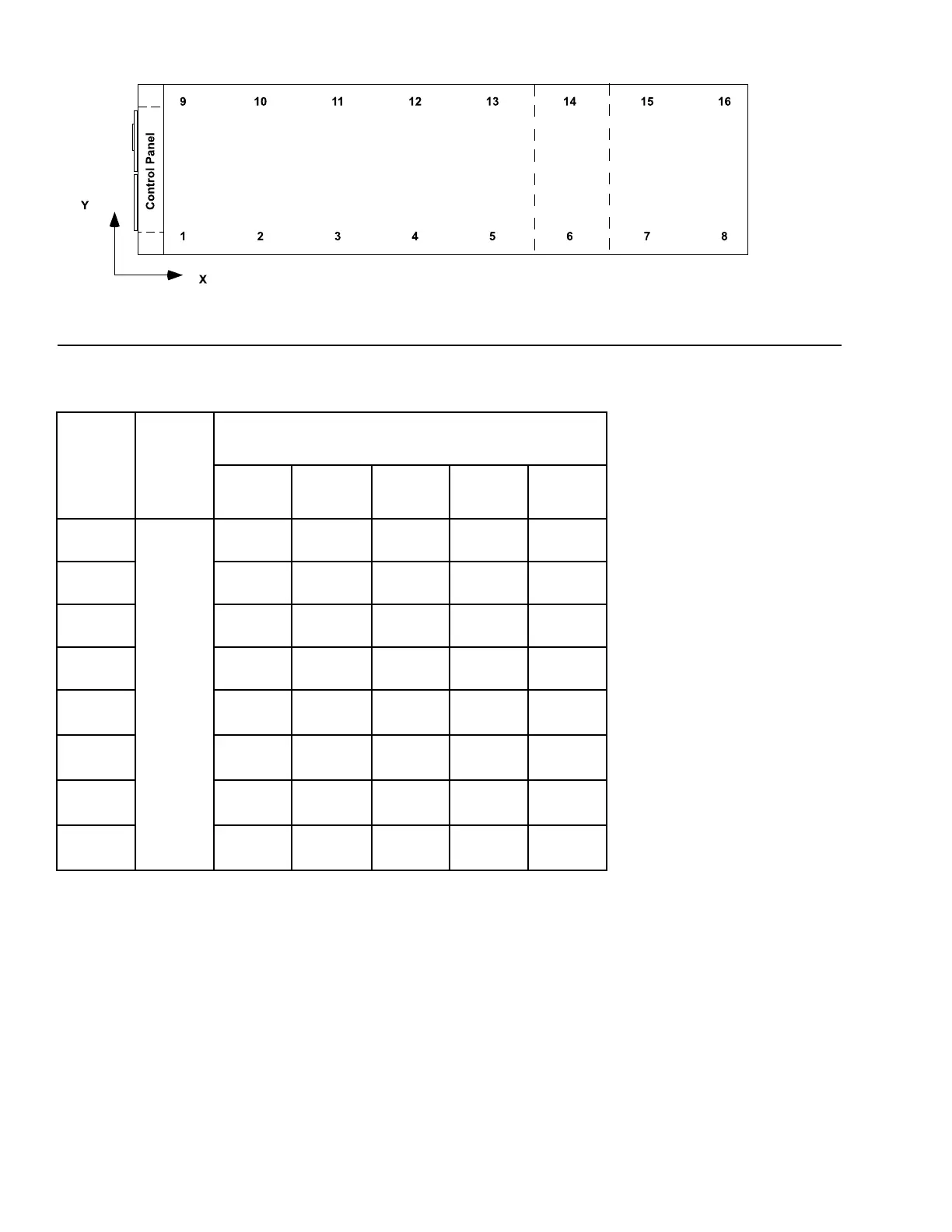
Table 10 - Isolator selection and mounting locations (cont'd)
Location
Isolator
Y-Dimen-
sion (All
YVAA
Models),
in. (mm)
Isolator X-Dimension listed by YVAA Model Designation,
in. (mm)
0361/1271 0391/1381 0456/1606 0399/1409 0469/1649
1
1.7
(43)
9.5
(242)
9.5
(242)
9.5
(242)
9.5
(242)
9.5
(242)
2 82.3
(2091)
82.3
(2091)
82.3
(2091)
82.3
(2091)
82.3
(2091)
3 142.6
(3622)
142.6
(3622)
142.6
(3622)
142.6
(3622)
142.6
(3622)
4 219.7
(5581)
219.7
(5581)
219.7
(5581)
219.7
(5581)
219.7
(5581)
5 300.1
(7621)
300.1
(7621)
300.1
(7621)
300.1
(7621)
300.1
(7621)
6 422.1
(10,721)
422.1
(10,721)
422.1
(10,721)
422.1
(10,721)
421.8
(10,712)
7 540.2
(13,721)
540.2
(13,721)
503.5
(12,789)
8 585.1
(14,861)
Notes:
1. Contact your nearest Johnson Controls Sales Oce for weight data.
2. All isolator mounting holes are 19 mm.
3. Dimensions are in inches (mm).
Figure 36 - Isolator selection and mounting locations