Page - 60/100 AE0ZP0EC - AC-0 SSL SENSORED - User Manual
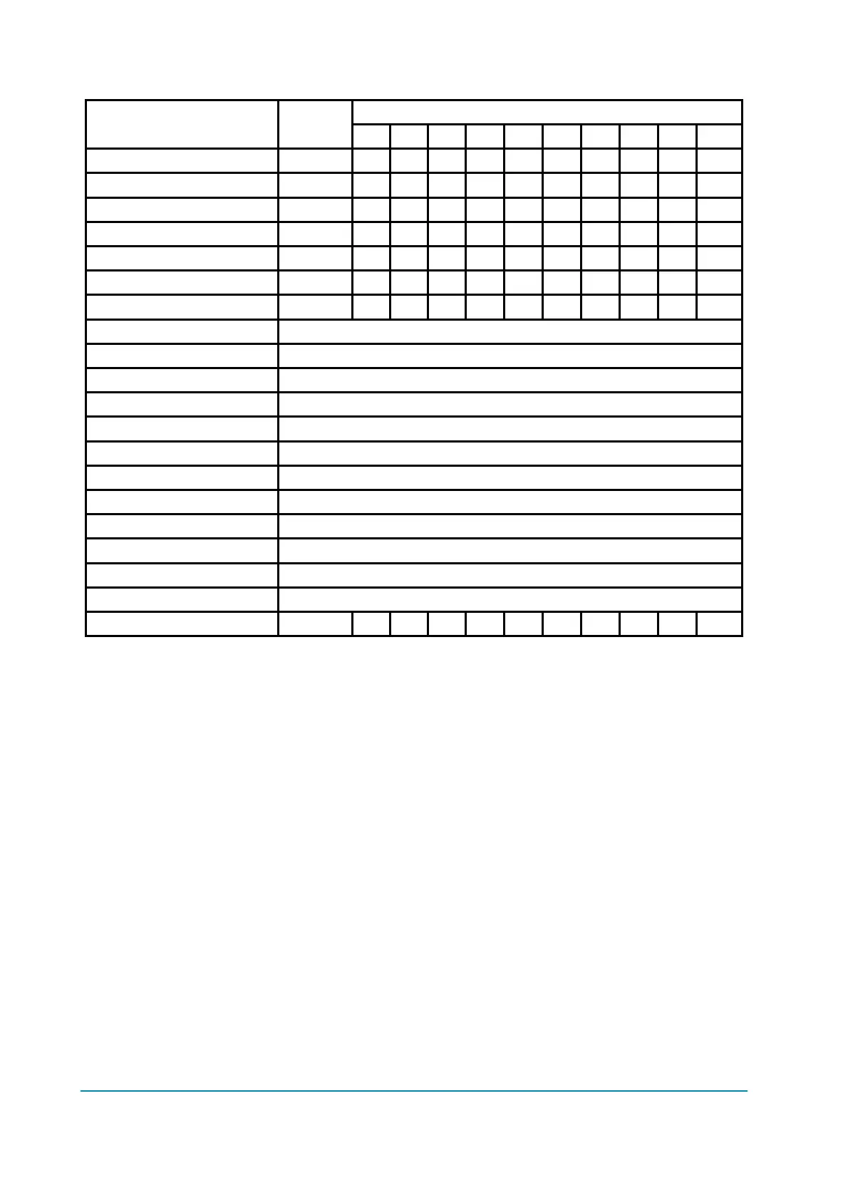
PROGRAMMED LEVEL
PARAMETER UNIT
0 1 2 3 4 5 6 7 8 9
ACCELER. DELAY (*) Sec. 2.05 3.00 3.05 4.00 4.05 5.00 5.05 6.00 6.05 7.00
DECELER. DELAY (**) Sec. 5.05 5.00 4.05 4.00 3.05 3.00 2.05 2.00 1.05 1.00
MAX SPEED LIFT (***) Hz - - - - - - - - - -
SPEED FINE (ALL) (***) Hz - - - - - - - - - -
CUTBACK SPEED %Max Sp 10 15 20 25 37 50 62 75 87 100
FREQUENCY CREEP Hz 0.3 0.6 0.9 1.2 1.5 1.8 2.1 2.4 2.7 3.0
MAXIMUM CURRENT %IMAX 47 53 58 64 70 76 82 88 94 100
AUXILIARY TIME Not used.
MIN VALVE 1 Not used.
MIN VALVE 2 Not used.
MAX VALVE 1 Not used.
MAX VALVE 2 Not used.
VALVES VOLTAGE Not used.
VALVE3 VOLTAGE Not used.
VALVE4 VOLTAGE Not used.
V1 OPENING RAMP Not used.
V2 OPENING RAMP Not used.
V1 CLOSING RAMP Not used.
V2 CLOSING RAMP Not used.
HYDRO DELAY Sec. 0.00 1.28 1.42 3.20 3.84 5.12 7.04 9.60 10.8 16.0
(*) The acceleration time shown is the time from 0 Hz to 100 Hz. This is the
ideal ramp calculated by the software; the real ramp could change as a
function of motor control parameter setting and, obviously, as a function
of the load.
(**) The braking feature is based upon deceleration ramps. The value shown
in the table is the time to decrease the speed from 100 Hz to 0 Hz. This
is the ideal ramps calculated by the software; the real ramp could
change as a function of motor control parameter setting and, obviously,
as a function of the load.
(***) Adjustable with a 1 Hz resolution in the 0 to 200 Hz range.