Page 7
fig. 8a fig. 8b
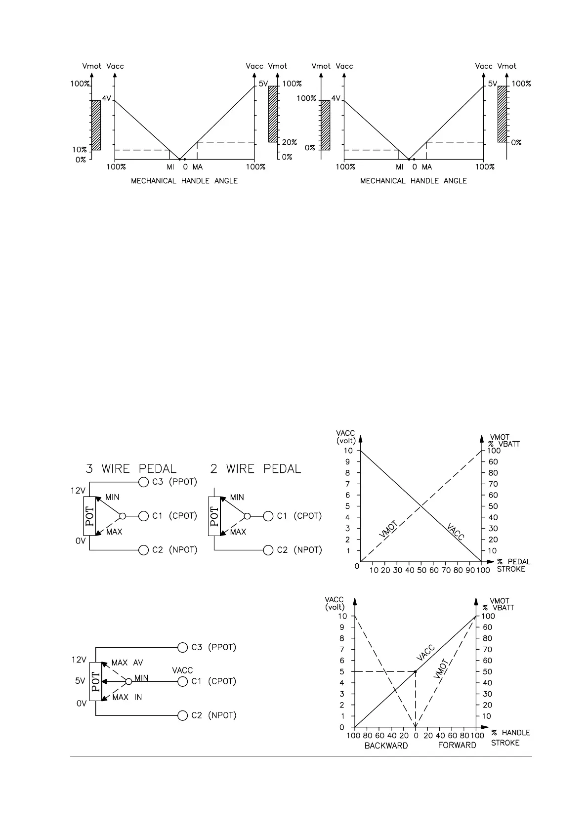
The two graphs show the output voltage from an uncalibrated potentiometer with re-
spect to the mechanical “zero” of the knob of one handle (MI and MA indicate the point
at which the speed microswitches close, 0 is the mechanical zero of the handle rota-
tion). The first graph (Fig. 8a) shows the correspondence of the motor voltage without
having made the acquisition, while the second graph (Fig. 8b) shows the same corre-
spondence after signal acquisition by the potentiometer. The acquisition procedure is
invalidated by the machine if the difference between the maximum value and the mini-
mum value is less than 2V.
This acquisition procedure makes it possible:
- to use “reversed” potentiometric signals, i.e. those which are carried from a high
initial value to a low final value.
- to use a normal potentiometer instead of one with central zero.
For the correct functioning of signal acquisition, it is absolutely necessary that the run-
ning microswitches be activated by the same shaft that moves the potentiometer.
Application examples.
- Signal overturn.
VACC = accelerator signal voltage to pin C1.
VMOT = percentage of batt. voltage on the motor.
- Central zero signal.
H2B general description