FDM Technical Data and Operating Instructions
3.4 Controls and Connectors
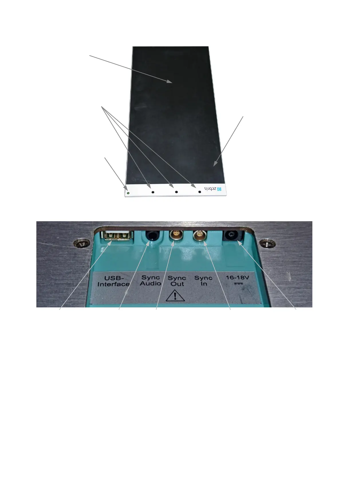
All cable connections between platform and PC will be established by the connector box
located at the bottom of the platform.
USB-socket Video-Sync Sync Out/Master Sync In/Slave Powersupply
3.5 Status indicator LED
green flashing The power supply unit is connected to mains and a correct sup-
ply voltage is provided. A USB connection is not established yet
or recognized. The platform is not ready for initialization or
measurement.
green permanent The power supply unit is connected to mains and a correct sup-
ply voltage is provided. A USB connection is established and
recognized. The platform is ready for initialization or measure-
ment.
orange permanent A measurement is in process.
orange / green flashing A measurement is in process and infrared synchronization sig-
nals (from other zebris devices) are received. The orange flash-
ing signalizes that valid synchronization signals are received.
Connector box
withsafety lock
(bottom side)