FDM Technical Data and Operating Instructions
4.3.3 Power Supply Unit SYNCLights
For operation of the SYNCLight plus a power supply unit needs to be connected.
REF-No. 33102210
Input Output Cable Length
100 - 240V AC 24V DC Mains Lead 1.7m
50 - 60Hz 110W DC-Lead 1.7m
SYNC-Modes
ESD - protected, voltage reversal proof input
Input resistance: 38K (AC)
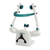
Signal-Level: AC
Trigger Level: 15mV
ESD - protected, voltage reversal proof input
The signal from the VIDEO SYNC IN is directly
transmitted to VIDEO SYNC OUT and can be
used for control of additional devices.
ESD - protected, voltage reversal proof input
Input resistance: 38K (Pull-Up)
VIH (High-Level Input Voltage): ≥ 3.7V
VIL (Low-Level Input Voltage): ≤ 3.0V
Both Signals can be used as Trigger input
(“AKTIV” as well as “CLK”) and possess the
same effect.
The signal switches the LED light on to the
brightness level pre-selected by the DIMMER
The SYNC IN is the standard synchronization
tool (zebris SYNC) of all zebris measuring sys-
tems and intended to be used to synchronize
the lighting system with the measuring signal of
other zebris measuring systems (e.g. CMS).
In order to use SYNC IN the SYNC mode
switch has to be set to position SYNC.
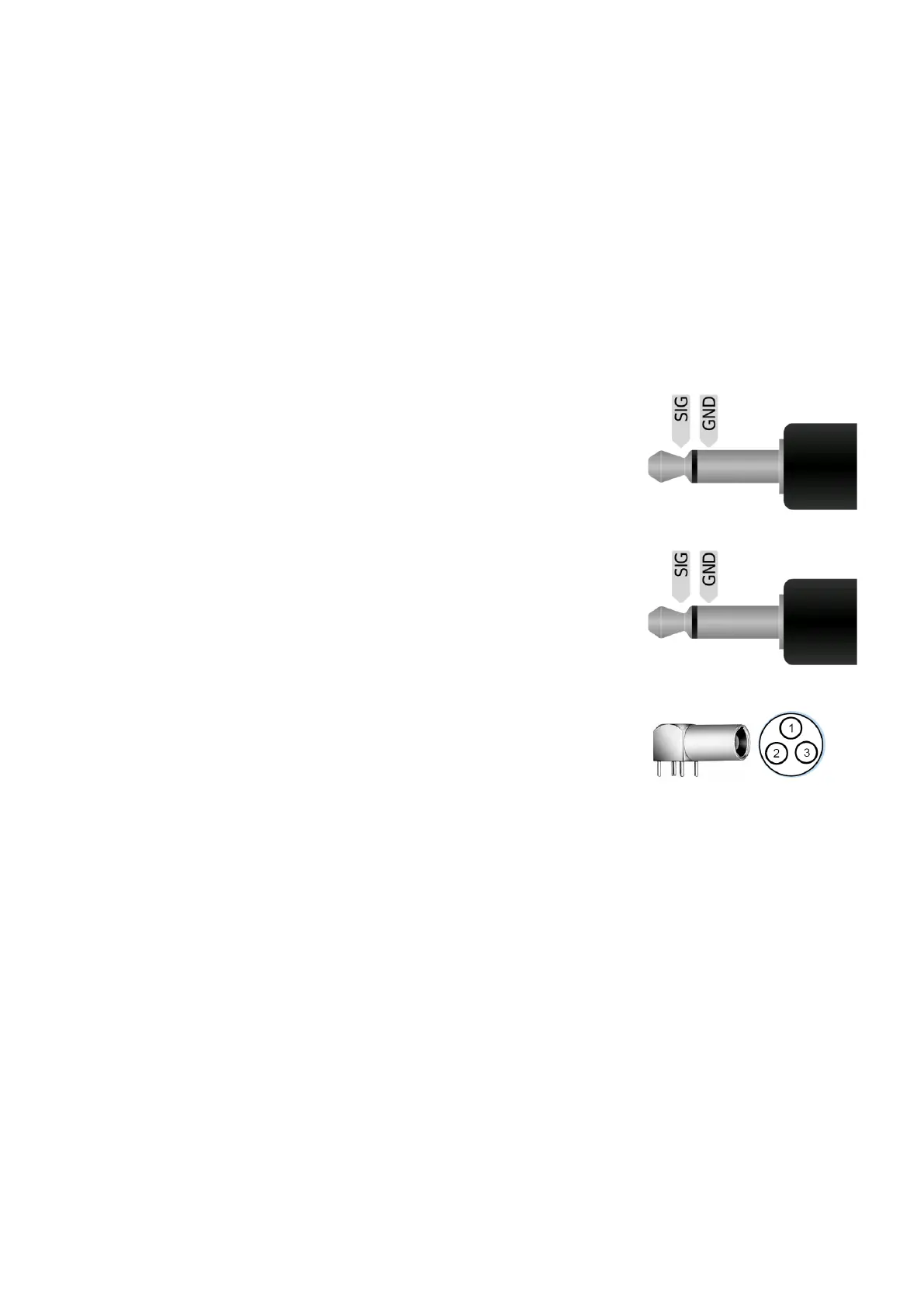
3-Pin Socket
Pin1: CLK
Pin2: AKTIV
Pin3: GND
Socket Type
LEMO- Part No.
FGA.00 303.CLADxxxx
 Loading...