EasyManua.ls Logo

zebris FDM-SX - Page 36

Default Icon
54 pages
Print Icon
To Next Page IconTo Next Page
To Previous Page IconTo Previous Page
Loading...
zebris Medical GmbH
FDM Technical Data and Operating Instructions
Page 36/54
Modes
Characteristics
Pin Assignment
PULSE
SYNC
ESD - protected, voltage reversal proof input
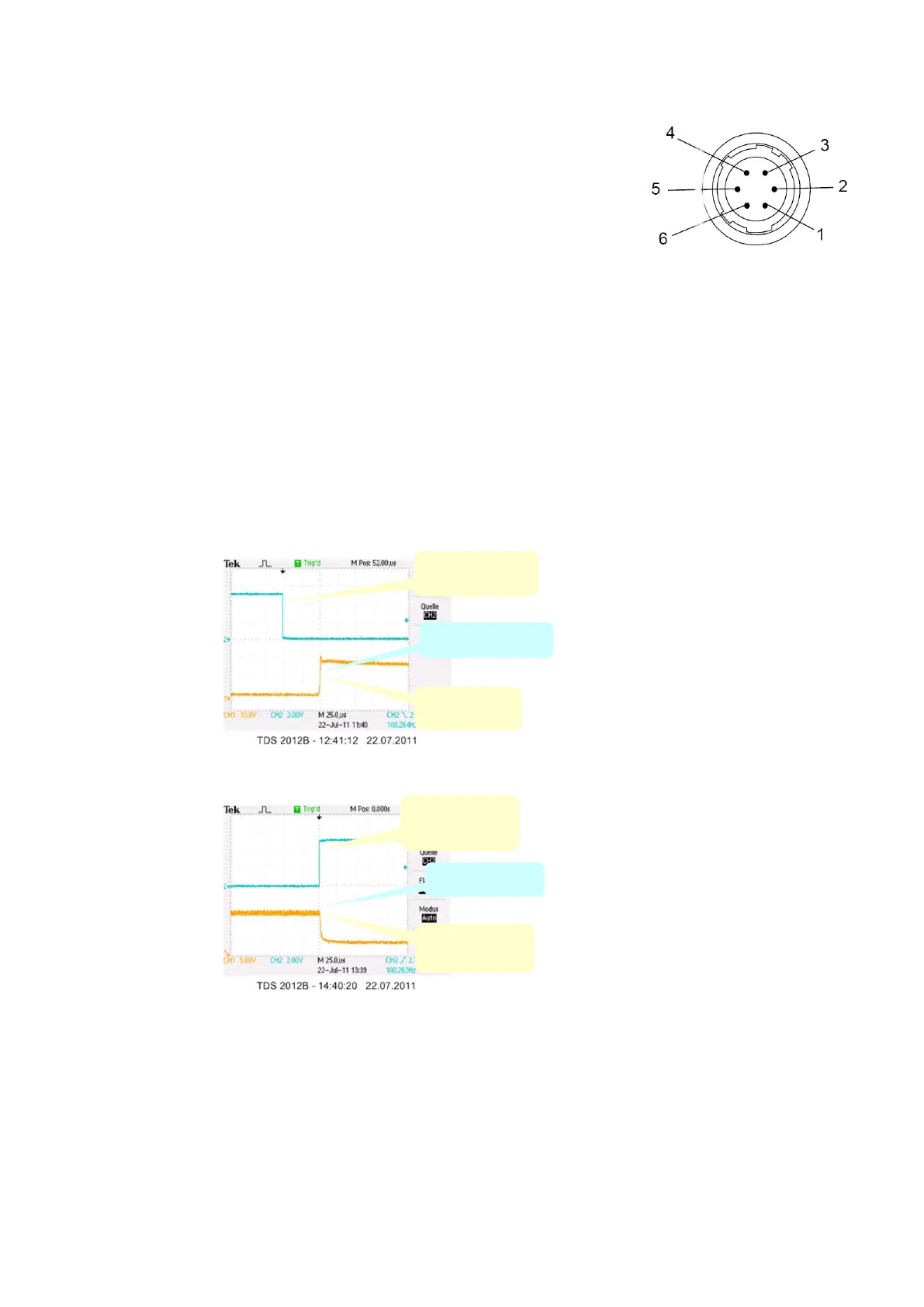
Input resistance: 2K (Pull-Up)
VIH (High-Level Input Voltage): 2.0V
VIL (Low-Level Input Voltage): 0.8V
Polarity: Lo Active
When mode PULSE SYNC is used LED bright-
ness is set to 150%.
The shutter output of industrial high speed cam-
eras can be used as trigger signal for the PULSE
SYNC.
By utilizing pulsed light optimal lighting conditions
for industrial cameras can be accomplished with-
out being too bright or disturbing for the human
eyesight.
In order to use PULSE SYNC the SYNC mode
switch has to be set to position SYNC.
6-Pin Socket
Pin4: Input
Pin5: GND
Socket Type
HIROSE HR10A-7P-6S
Camera Trigger
Input
Begin of
Illumination
Timing Properties when
switching the Light ON:
Delay of 50µS
The cameras Trigger-Output
should be preset to this Value.
Delay: 50µS
Camera Trigger
Input
End of
Illumination
No Delay!
Timing Properties when
switching the Light OFF:
No Delay (0µS)
No adjustment of
Trigger-Output necessary!

Table of Contents

Related product manuals