SPI1021 12570-0701-07 Page
/ 24 www.ziehl.de
9.15 Simulation
Here, the voltage, frequency or a vector surge can be simulated and the setting can be tested. All 3 phases
plus the 10 minute mean value are always simulated. All functions of the device operate as if this value is
actually being measured. Alarm and error messages are only indicated with the LEDs and not in the display.
The set values are simulated until the menu item si . is exited with the or button. If the SPI1021 is
sealed/locked, simulation is not possible.
If the section switch feedback contacts are connected to the SPI1021 and enabled, (set value > section-
switch turn-on time under 8trel.8), after a shut-down, the tripping time (dAL + time of slowest section switch)
is displayed.
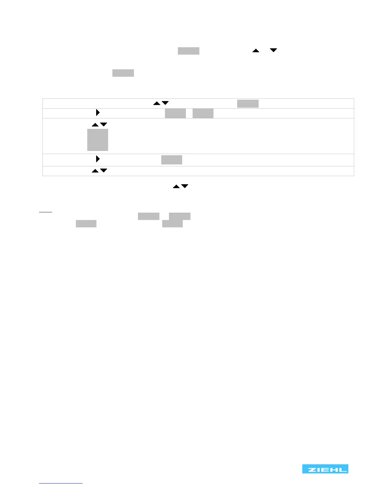
Adjustment process:
• Select the menu item with the buttons until display 8si .8
• Press the button 1x display 8si 8 / 8u 8
• Use the buttons to set the measurement factor for simulation:
o 8u 8 Voltage + 10min mean value (frequency = last simulated value)
o 8f 8 Frequency (voltage = last simulated value)
o 8vsr 8 Vector shift
• Press the button 1x display 8 2308 (selected measurement factor is simulated)
• Use the buttons to set the desired value
After exiting the Simulation menu item with the buttons, the unit switches over to monitoring the limits.
The unit automatically returns to the display mode if no button is pressed for 15 minutes.
Hint: A limit value should be tested that is higher than the set 10min mean value. If the 10min mean value has
to be temporarily switched off, set (8Um .8 8 off.8 since otherwise it will trip first. The same applies, for
example, for U, , during a simulation of U,, .
 Loading...