Do you have a question about the ZKTeco MA500 and is the answer not in the manual?
Describes the process of mounting the device on a wall.
Explains the core functionalities and features of the access control system.
Important safety warning regarding connecting the lock with power.
Details on connecting the device and lock using a shared power supply.
Details on connecting the device and lock using separate power supplies.
Explains connections with alarm, exit button, and door sensor.
Instructions for connecting the device to a DC 12V power supply.
Information on connecting to third-party access control panels via Wiegand.
Details on using RS485 for communication and connecting RS485 readers.
How to connect RS485 readers and use the device as a master.
Explains TCP/IP connectivity via crossover or straight-through cables.
Recommended procedure for initial setup, user registration, and system operation.
Guides for changing administrator password and recovering forgotten passwords.
Method to open the door using the administrator password.
Process for registering individual users' fingerprints or cards.
Guide for registering multiple cards in batches.
How to back up registered user data like fingerprints, cards, and passwords.
Describes the process of authenticating users via fingerprints, cards, or passwords.
Steps for deleting a specific user's registered data.
Procedure to delete all registered users from the system.
Visual guide on how to perform the 'Delete All Users' operation.
How to set the duration for which the door remains unlocked.
Details on selecting different user authentication methods.
Instructions for enabling or disabling the stealth mode for the indicator light.
How to configure the device to work with door sensors (NONE, NO, NC).
How to enable or disable various alarm settings for the device.
Setting up alarms for incorrect operation attempts.
How to enable or disable the tamper alarm for device disassembly.
Setting the delay for checking the door sensor status to trigger alarms.
Information on connecting external fingerprint readers via RS485.
Supported Wiegand output formats and configuration.
Details on the device's capacity for users and fingerprint templates.
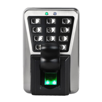
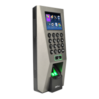
The ZKTeco MA500 is an advanced biometric and RFID access control system designed for secure and efficient door management. This device integrates multiple authentication methods, including fingerprint, card, and password verification, offering a flexible and robust solution for various access control needs. Its primary function is to regulate entry by verifying registered users, triggering a lock control relay to open the door upon successful authentication.
The MA500 serves as a comprehensive access control unit, capable of managing user access and monitoring door status. When a registered user is successfully verified, the device activates the lock control relay, allowing the door to open. This core function is complemented by several security features. A door sensor detects the on-off state of the door, enabling the system to trigger an alarm if the door is unexpectedly opened or improperly closed. Furthermore, the device is equipped with a tamper alarm that activates if the unit is illegally removed, enhancing physical security.
The system supports external connectivity, allowing for integration with other access control components. It can connect to an external card reader, expanding the range of authentication options. An external exit button can also be integrated, providing a convenient way to exit from the secured area. For centralized management, the MA500 supports RS485 and TCP/IP communication protocols, enabling a single PC to manage multiple devices. This network capability facilitates remote control and information exchange with PC software, such as ZKAccess3.5.
The MA500 can operate in different lock connection modes, supporting both Normally Open (NO) and Normally Closed (NC) locks. It is crucial to ensure correct wiring and to use a FR107 diode in parallel with electrical locks to prevent self-inductance EMF feedback, safeguarding the system from potential damage. The device can share power with the lock or use a separate power supply for both the device and the lock, offering flexibility in installation based on power requirements and distance between components.
The MA500 offers a user-friendly interface for configuration and daily operation. To enter the system setting mode, users press * #, followed by the system password and #. A green status light and a beep sound confirm entry into the setting mode. The system automatically exits the setting mode after 20 seconds of inactivity, ensuring security. The * key is used to exit operations, while the # key confirms selections.
User management is a key feature, allowing administrators to add, authenticate, and delete users. The administrator password can be changed for enhanced security, and in case of a forgotten password, a specific procedure involving the magnet tamper switch can restore the initial administrator password and factory settings.
Adding users can be done individually by registering fingerprints, cards, or passwords, or in batches for series cards. When registering users, the device automatically increments user IDs and guides the process with visual and auditory feedback (green light for success, red light and beeps for failure). The system also supports backing up registered user data, including fingerprints, passwords, or cards, ensuring data integrity.
User authentication is straightforward: after power-on, the device enters an authentication state, ready for users to unlock the door using their registered fingerprints, cards, or passwords. The system provides clear feedback on authentication success (green light) or failure (red light and beeps). It also supports duress passwords and emergency passwords, offering additional security layers in critical situations.
Access control parameters can be configured to suit specific security requirements. The unlocking duration can be adjusted, and various authentication modes are available, including only password, only RF card, only fingerprint, or combinations thereof (fingerprint/password/RF, RF&password, fingerprint&password). This flexibility allows for tailored security levels depending on the environment.
The MA500 also features a stealth mode, which, when enabled, turns off the indicator light, making the device less conspicuous. The door sensor mode can be configured as NONE (sensor not used), NO (lock open when door open), or NC (lock closed when door closed), providing adaptability to different door types and security preferences.
The MA500 incorporates several alarm functions to enhance security and alert administrators to potential issues. The alarm setting can be enabled or disabled, and when enabled, it activates error operation-triggered alarms, tamper alarms, and door status sensor delays.
The error operation-triggered alarm is activated if an administrator fails authentication three times, preventing further authentication attempts for a short period. The tamper alarm is designed to trigger if the device is disassembled, providing a deterrent against unauthorized physical tampering.
The door status sensor delay (DSen. Delay) allows for a configurable delay in checking the door sensor after the door opens. If the door sensor state deviates from the normal state set by the door sensor switch after this delay, an alarm is generated. When an alarm is triggered, the device first beeps internally, followed by an external alarm after approximately 30 seconds. Alarms can be stopped by a valid user performing verification or if the door sensor state returns to its coordinated set state.
The device's communication capabilities, including RS485 and TCP/IP, facilitate remote monitoring and maintenance through PC software. This allows for centralized management of multiple devices, firmware updates, and troubleshooting without direct physical interaction with each unit. The ability to set RS485 addresses for external readers and configure Wiegand output formats ensures compatibility and seamless integration with existing access control infrastructures. The MA500's robust design and comprehensive feature set aim to provide a reliable and manageable access control solution.
| Type | Basic access control reader |
|---|---|
| Log capacity | 100000 |
| Product color | Black, Silver |
| Cards capacity | 30000 cards |
| Number of users | 3000 user(s) |
| Fingerprint reader | Yes |
| Authentication type | Access chip/card, Biometric, Password |
| Keypad number of keys | 12 |
| International Protection (IP) code | IP65 |
| Sensor type | - |
| Operating temperature (T-T) | 0 - 45 °C |
| DC current (max) | 3 A |
| RS-485 ports | 1 |
| PC connection | RS-485/RJ-45 |
| Built-in display | No |
| Depth | 127 mm |
|---|---|
| Width | 83 mm |
| Height | 74 mm |