SA40 User Manual
Page | 7 Copyright©2021 ZKTECO CO., LTD. All rights reserved.
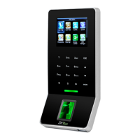
(1) The device and the lock share the power supply, as shown in Figure 1-1:
Note: U
LOCK
= 12 V, I ≥ I
DEVICE
+ I
LOCK
, and the lock is close to the device.
Figure 1-1
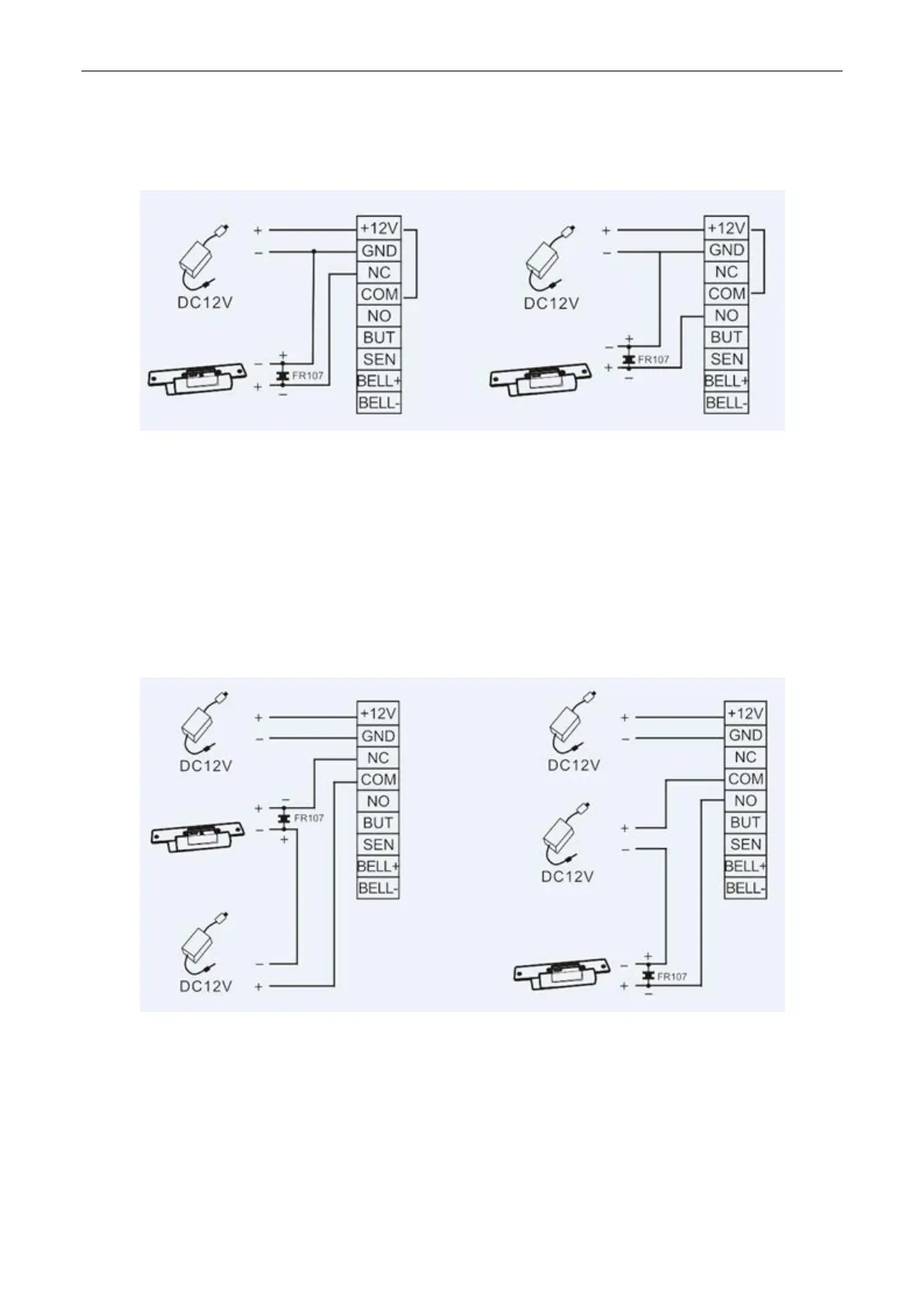
(2) The device and the lock do not share the power supply, as shown in Figure 1-2:
Note:
① U
LOCK
= 12 V, and I < I
DEVICE
+ I
LOCK
② Or U
LOCK
≠ 12 V
③ Or the lock is far from the device.
Figure 1-2
I indicates the output current of the device power supply, U
LOCK
indicates the operating voltage of the lock,
and I
LOCK
indicates the operating current of the lock.