SA40 User Manual
Page | 6 Copyright©2021 ZKTECO CO., LTD. All rights reserved.
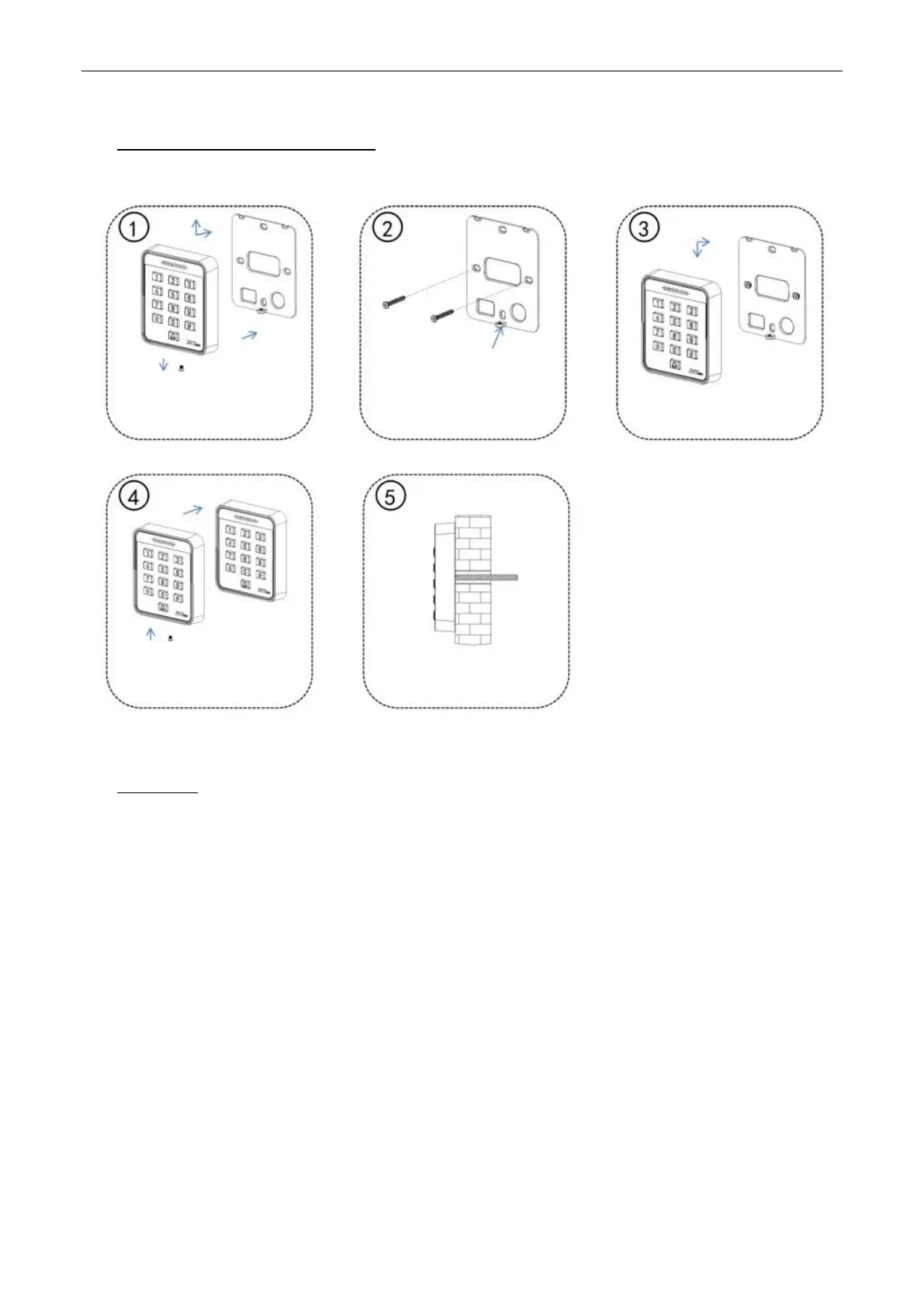
1 Installation Diagrams
2 Wiring
Warning: Do not connect wires when the power is on!
Note:
① This device supports normally open (NO) and normally close (NC) locks which can be connected to
different terminals for different functions.
② At the moment when the electric lock is turned on or off, the electric lock generates a self-induced
electromotive force. To prevent the impact of the self-induced electromotive force on the access control
system, it is necessary to connect an FR107 diode in parallel to the electric lock during wiring on the access
control system to release the self-induced electromotive. The FR107 diode is randomly provided. Do not
reverse its positive and negative poles.
③ If an extension cable needs to be connected between the all-in-one device and the controller, we
recommend that you use a Category 6 or above unshielded network cable; otherwise, voltage drop may
occur on the extension cable, resulting in an unstable card reading effect.
In the arrow directions shown
above, remove the screws, and
remove the rear hanging plate from
the device
Place the side of the rear hanging
plate with screw holes downward
Align the screw holes on the rear
hanging plate with the holes drilled
on the wall, and fix the rear hanging
plate onto the wall with screws
Sort out and connect the cables,
and install the device onto the
rear hanging plate
Use the screws removed in Step 1
to fix the device onto the rear
hanging plate
Pass the device cables through
the wall and install them