11
12
2
11
16
75
3
9
62
60
20
B
10
1
1
27
28
A
76
9
8
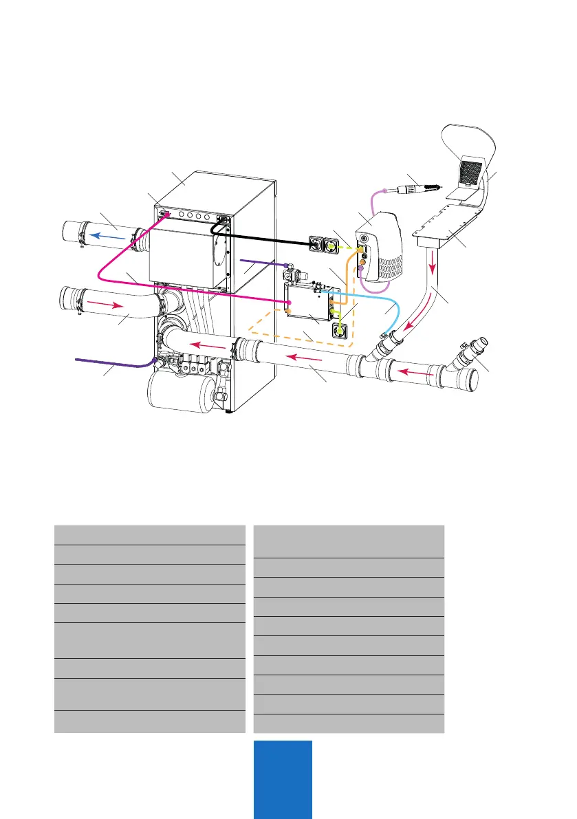
Fig. 11: Schematic layout of a
workstation with multistation suction
system Z4 VARIOmatic
1 Pipe system
2 Suction hose workstation
3 Port valve
8 Comp. air line port valve
9 Comp. air supply
10
Handpiece control unit
e.g. Zubler K50
11 Handpiece
12
Power cord handpiece
control unit (with 28 only!)
16 Exhaust hose Ø75mm
20
Z4 VARIOmatic Multi-
station suction unit
27 Connectors AP601
28 Start signal K50
60 Autom. port opener AP601
62 Mains cable AP601
75 Network cable
76
Power cord K50
A Suction funnel R2200
B Rectangular pipe R2000
1.4 Connecting the AP601 port openers