12
8
7
5
6
4
5
61
63
72
69
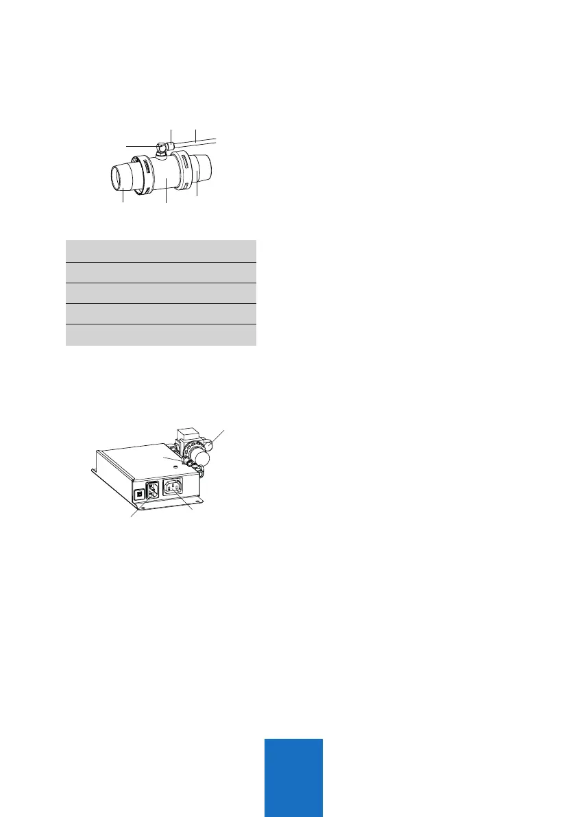
1.4.1 Install the port valve
Q Plug the port valve (3) directly into the
40mm branch pipe.
Q
Connect the port valve and the workstation
with 40mm hose. The Length should not
exceed 1.5m.
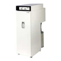
1.4.2 Install the control unit
Q Install the control unit with at least 2
screws at the workbench close to the
workstation.
Q Connect the compr. air connector (6) of
the port valve with the compr. air connector
(72) of the AP601 control unit, using the
enclosed Ø6mm compr. air hose.
Q Connect the compr. air supply (69) of the
AP601 control unit (pressure reducer) with
your local compr. air supply, using the
enclosed Ø8mm compr. air hose.
Q Plug the handpiece or other tool into the
IEC C13 socket (63), using the enclosed
C13/C14 power cord adapter.
Q If your working equipment is not equipped
with a C13 socket, you may need a suitable
power adapter which is not included.
Q Plug the enclosed power cord into the
IEC C14 power socket (61) of the AP601
control unit and plug it into a local power
socket.
Fig. 12
Fig. 13
4 Valve body
5 Suction ports Ø40mm
6 Compr. air connector
7 Push ring
8
Compr. air hose Ø6mm