Touchscreen User Manual – Issue 1
Zytronic X-Y Controller (Serial and USB) 28
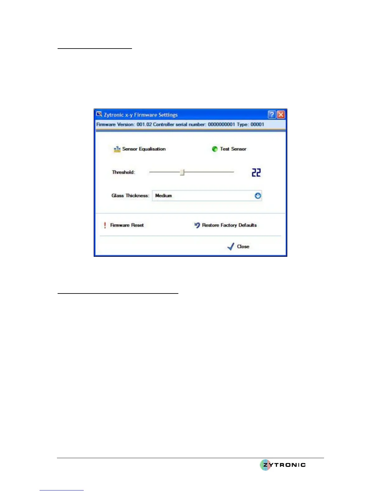
Step 1 – Firmware Settings
• With the UPDD console open, select the Hardware tab, then click on the Firmware Settings
icon. This will open the controller Firmware Settings page, as shown in Figure 25. The
Firmware Settings page allows the user to test the sensor operation, set vital parameters such
as the sensitivity of the touchscreen to an applied touch and also to specify if the touchscreen
is to operate as a Direct Touch or Through Touch mode (i.e. operate through different
thicknesses of glass overlays).
Figure 25: Controller Firmware Settings Page
Step 2 – Testing the Touchscreen Operation
• Click on the Test Sensor icon.
• Launching the Test Sensor page displays the x and y sensor wire array matrix levels.
Applying a touch to the sensor will register a response in the x and y wires levels. This graph
can be used to determine the correct operation of all the wires within the sensor. This can be
done by applying a touch to the sensor and moving your finger left to right then top to bottom
over the sensor. All wires should register a peak relative to your finger movement across the
sensor, as shown in Figure 26. Please note: touch operation is disabled when the Test Sensor
page is open. The Test Sensor page can be terminated by using the Escape key via a
connected keyboard or using a mouse to press the Close button located in the bottom right
hand corner of the page.
• If any of the x and y wire levels do not move when a touch is applied and moved left and
right, top and bottom across the screen then this may indicate a fault and the user should seek
further advise from the vendor which the touchscreen was purchased from.
• If x and y wire levels are randomly moving to levels above 3 to 4 without an applied touch
this may indicate that the system may require better grounding or the sensor needs to be
spaced further away from the LCD to minimise the noise levels. Random level fluctuations
of 1 to 2 with occasional high peaks are normal.
• Now close the Test Sensor page by clicking on the Close button in the right hand corner of
the page.