Chapter 1 VMG Introduction
VMG4005-B50B User’s Guide
10
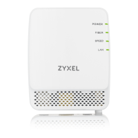
1.4.2 LEDs (Lights)
The following table describes the LEDs.
None of the LEDs are on if the VMG is not receiving power.
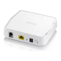
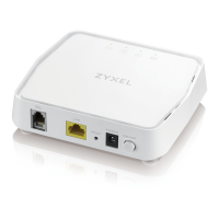
1.4.3 Bottom Panel
The connection ports are located on the bottom panel. The following graphic display the bottom panel.
Figure 3 Bottom Panel
The following table describes the items on the bottom panel.
1.4.4 RESET Button
If you forget your password or cannot access the Web Configurator, you will need to use the RESET
button at the back of the device to reload the factory-default configuration file. This means that you will
Table 1 LED Descriptions
LED COLOR STATUS DESCRIPTION
Power
Green On The VMG is receiving power and ready for use.
Blinking The VMG is in the booting state and getting ready for use.
Red On The VMG detected an error while self-testing, or there is a device
malfunction.
Blinking The VMG is uploading firmware.
Off The VMG is not receiving power.
DSL1
DSL2
Green On The ADSL/VDSL line is up.
Blinking The VMG is initializing the ADSL/VDSL line.
Off The DSL line is down.
Ethernet
Green On The VMG has a successful 10/100/1000 Mbps Ethernet connection with a
device on the Local Area Network (LAN).
Blinking The VMG is sending or receiving data to/from the LAN at 10/100/1000
Mbps.
Off The VMG does not have an Ethernet connection with the LAN.
Bottom Panel Ports
LABEL DESCRIPTION
DSL Connect a RJ-11 cable to the DSL port for Internet access.
LAN Connect a router/gateway to the Ethernet port for Internet access.
Reset Press the button to return the VMG to the factory defaults.
Power Connect the power adapter and then can press the power button to start the VMG.
 Loading...