Installation Requirements and Recommendations 21
installing WX switches or MAP access points. A network plan provides the
following information:
■ Number of WX switches required at your site, and where to install
them
■ Number of MAP access points required for adequate WLAN capacity
in each coverage area, and where to install them
■ Configuration settings for all the WX switches and MAP access points
in the WLAN, which can be automatically deployed to the devices by
3Com Wireless Switch Manager.
(For information about installing 3Com Wireless Switch Manager and
creating and verifying a network plan, see the Wireless LAN Switch
Manager Reference Manual.)
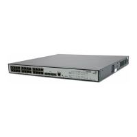
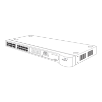
Installation Location WX1200 switch fans are located in the rear of the switch and air inlets
are located on the sides of the switch. Make sure these areas have
adequate ventilation after installation. Do not block air vents.
WARNING: The WX switch has been designed and tested to be installed
in an operating ambient temperature of 0° C to +50° C (32° F to 122° F).
To reduce the risk of equipment damage, install equipment with
consideration to these ambient conditions.
Cable Requirements To avoid installation problems, use the proper cables.
WARNING: The gigabit Ethernet fiber-optic interfaces use Class 1 lasers.
To reduce the risk of eye injury, do not stare into the interface or
otherwise direct the laser beam into your eye.
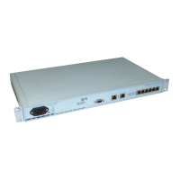
Serial Console Cable
The serial console port has a female DB-9 connector and supports the
EIA-232D signaling standard. You need a standard
DB-9-male-to-DB-9-female PC modem cable. Table 5 lists the pin signals.
 Loading...