TroubleshootingGuide
5|Page
3.NORMALOPERATION
Becomingfamiliarwithhowatanklesswaterheaternormally
operates may help to figure out what is wrong with it.
Assuming it is properly installed with appropriate gas, water,
and electric connections, the following is how it should
operate:
1) ACTIVATION
a. Ahotwatertapisopenedenoughthattheflow
sensordetectsaflowratethroughtheheatergreater
thantheactivationpointof0.75gpm.
b. Thefanactivatesafterflowisdetected.
c. Thecomputerchecksforanyproblemswiththeunit
beforestartup.
d. Igniteractivates.You
canhearthebuzzingofthe
sparkigniter.
e. Maingasvalve,proportionalvalve,andsolenoidgas
valveswillopen.Youwillhearadeep“clunkclunk”
noise.
f. Onceaflameisdetected,theredLEDlocatedonthe
computerboardwillactivate.
g. Inamulti‐he ater setup,
thecontrollerwillactivatethe
nextheaterin2‐4gpmincrements,dependingonthe
settemperature.
2) OPERATION
a. Theproportionalgasvalvewillmodulatebasedontheamountofhotwaterdemandedandthe
temperatureriseneeded.Thefanspeedwillmodulateaswelltocreateanefficientburn.
b. Youwillnoticethatonlypartialsectionsoftheburnerwillbelit.Thisisnormaloperation;there
arethreesectionsontheburnerassembly,andthecomputercontrolstheamountof sections
neededbasedontheflowrateandtemperatureriserequired.
3) SHUTDOWN
a. Theheaterwillshutdownwhenthewaterflowratedropsbelowthedeactivationpointof
0.4gpm.
b. Theheaterwillclosethemaingasvalveandsolenoidgasvalves,extinguishingtheflame.
c. WhentheflamedisappearstheredLEDwillturnoff.
d. Thefanwillincrease
inspeedtopurgetheventingofanyremainingexhaustgases.Thelength
ofpost‐purgecanlastupto1½minutes.
e. Theheatergoesintostandbywaitingfortheprocesstobeginagain.
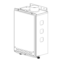
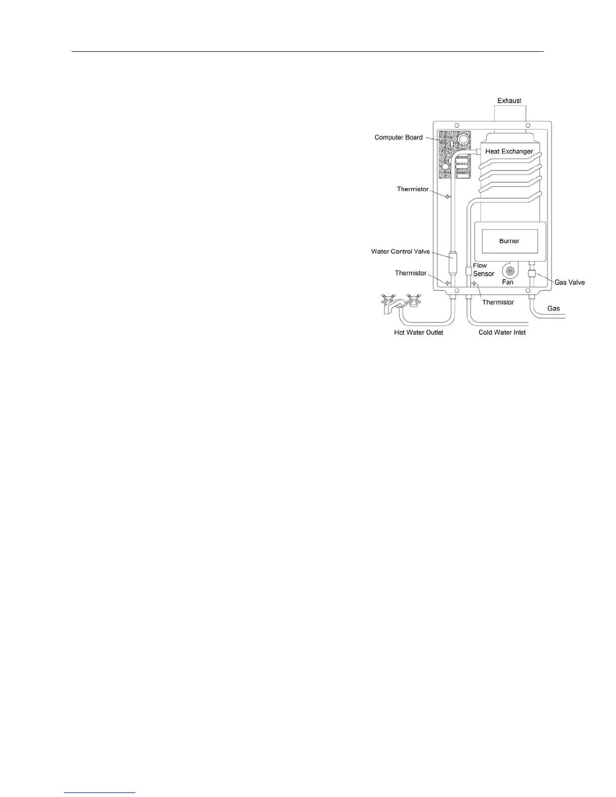
*Thepurposeofthisdiagramistoillustratethe
tanklesswaterheaterdesignconcepts,and
maynotbeaccuratetoyourmodelsphysical
description.
Figure2