MODGAS-XWR2 Technical Guide
TROUBLESHOOTING
33
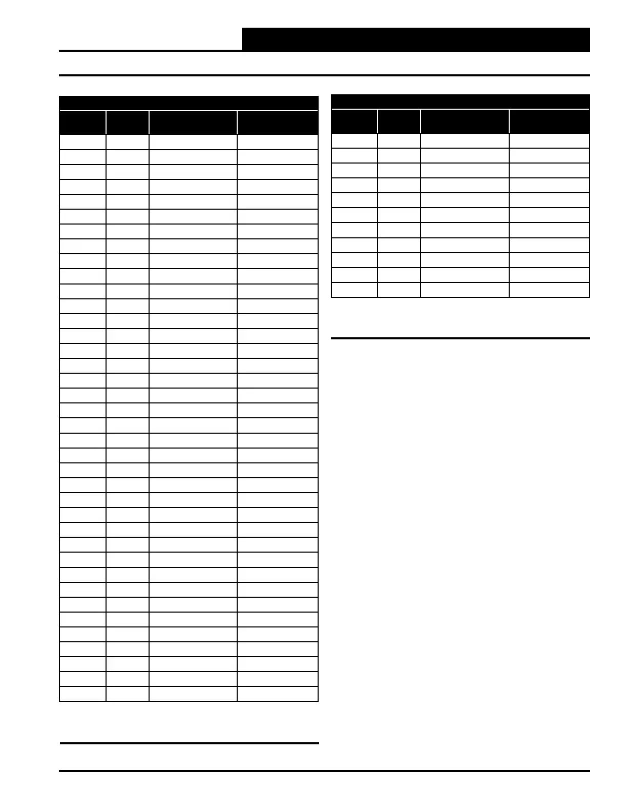
Table 6, cont.: 0-5V Temperature Sensor - Voltage
& Resistance for Type III Sensors
Thermistor Sensor Testing Instructions
1.) Use the resistance column to check the thermistor sensor while
disconnected from the controllers (not powered).
2.) Use the voltage column to check sensors while connected to pow-
ered controllers. Read voltage with meter set on DC volts. Place the “-”
(minus) lead on GND terminal and the “+” (plus) lead on the sensor
input terminal being investigated.
If the voltage is above 5.08 VDC, the sensor or wiring is “open.” If the
voltage is less than 0.05 VDC, the sensor or wiring is shorted.
Temperature to Resistance/Voltage Chart
Temp
(°F)
Temp
(°C)
Resistance (Ohms) Voltage @
Input (VDC)
-10 -23.3 93333 4.620
-5 -20.6 80531 4.550
0 -17.8 69822 4.474
5 -15.0 60552 4.390
10 -12.2 52500 4.297
15 -9.4 45902 4.200
20 -6.7 40147 4.095
25 -3.9 35165 3.982
30 -1.1 30805 3.862
35 1.6 27140 3.737
40 4.4 23874 3.605
45 7.2 21094 3.470
50 10.0 18655 3.330
52 11.1 17799 3.275
54 12.2 16956 3.217
56 13.3 16164 3.160
58 14.4 15385 3.100
60 15.6 14681 3.042
62 16.7 14014 2.985
64 17.8 13382 2.927
66 18.9 12758 2.867
68 20.0 12191 2.810
69 20.6 11906 2.780
70 21.1 11652 2.752
71 21.7 11379 2.722
72 22.2 11136 2.695
73 22.7 10878 2.665
74 23.3 10625 2.635
75 23.9 10398 2.607
76 24.4 10158 2.577
78 25.6 9711 2.520
80 27.8 9302 2.465
82 27.8 8893 2.407
84 28.9 8514 2.352
86 30.0 8153 2.297
88 31.1 7805 2.242
90 32.2 7472 2.187
95 35.0 6716 2.055
Temperature Sensor Resistance/Voltage Chart
Temperature to Resistance/Voltage Chart
Temp
(°F)
Temp
(°C)
Resistance (Ohms) Voltage @
Input (VDC)
100 37.8 6047 1.927
105 40.6 5453 1.805
110 43.3 4923 1.687
115 46.1 4449 1.575
120 48.9 4030 1.469
125 51.7 3656 1.369
130 54.4 3317 1.274
135 57.2 3015 1.185
140 60.0 2743 1.101
145 62.8 2502 1.024
150 65.6 2288 0.952
Table 6: 0-5V Temperature Sensor - Voltage &
Resistance for Type III Sensors
 Loading...