APPENDIX A
MODGAS-XWR2 Technical Guide
34
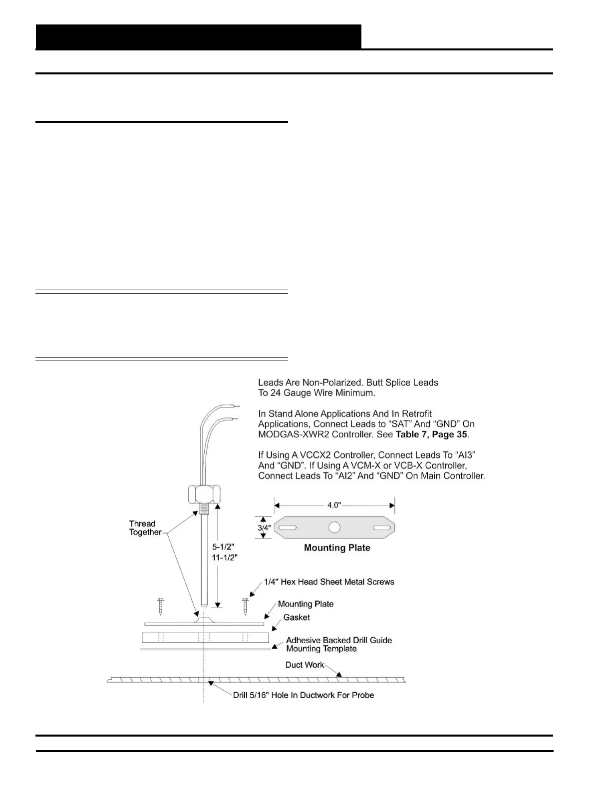
Supply Air Temperature Sensor Installation
Mounting the Supply Air Temperature
Sensor
• The Supply Air Temperature (SAT) Sensor should be
located in the duct-work downstream of the unit supply
air connection.
• Locate the sensor in the center of the widest part of the
duct. Use the supplied template and a 5/16” drill to make
a hole for the sensor.
• Install the gasket over the probe and mount securely to
the duct using the supplied sheet metal screws. Be sure
the gasket is compressed to provide an air tight seal.
• For best accuracy, apply insulation on the outside of the
duct, over the sensor. This will help prevent thermal
gradients from aecting the sensor.
WARNING: Make sure your Supply Air Temperature
Sensor is mounted and wired according to
these instructions prior to testing the unit or
else the modulating valve will not control
properly and may damage your equipment.
Figure 17: Supply Air Temperature Sensor Installation
Stand-Alone Mode
In Stand-Alone Mode, the SAT Sensor is connected to the MODGAS-
XWR2 Controller. If, in Stand-Alone Mode, the MODGAS-XWR2
Controller is used in conjunction with a Stand-Alone MHGRV
Controller, the SAT sensor is shared between the two controllers and
always attaches to the MODGAS-XWR2 Controller.
See Table 8, page 35 for SAT Options Jumper Settings and see
Figures 2, 3, 5 & 7 for wiring. See Table 7, page 35 for details
about retrot applications.
Communication Mode
When communicating with AAON Unit Controllers, the SAT Sensor
will be connected to the Main Controller. The exception would be
in retrot applications with older controllers. See Table 9, page 35
for SAT Options Jumper Settings and see Figures 9, 10, 11 & 13 for
wiring. See Table 7, page 35 for details about retrot applications.
 Loading...