COMMUNICATING WIRING
MODGAS-XWR2 Technical Guide
14
2V2IGN2S - Communicating Wiring
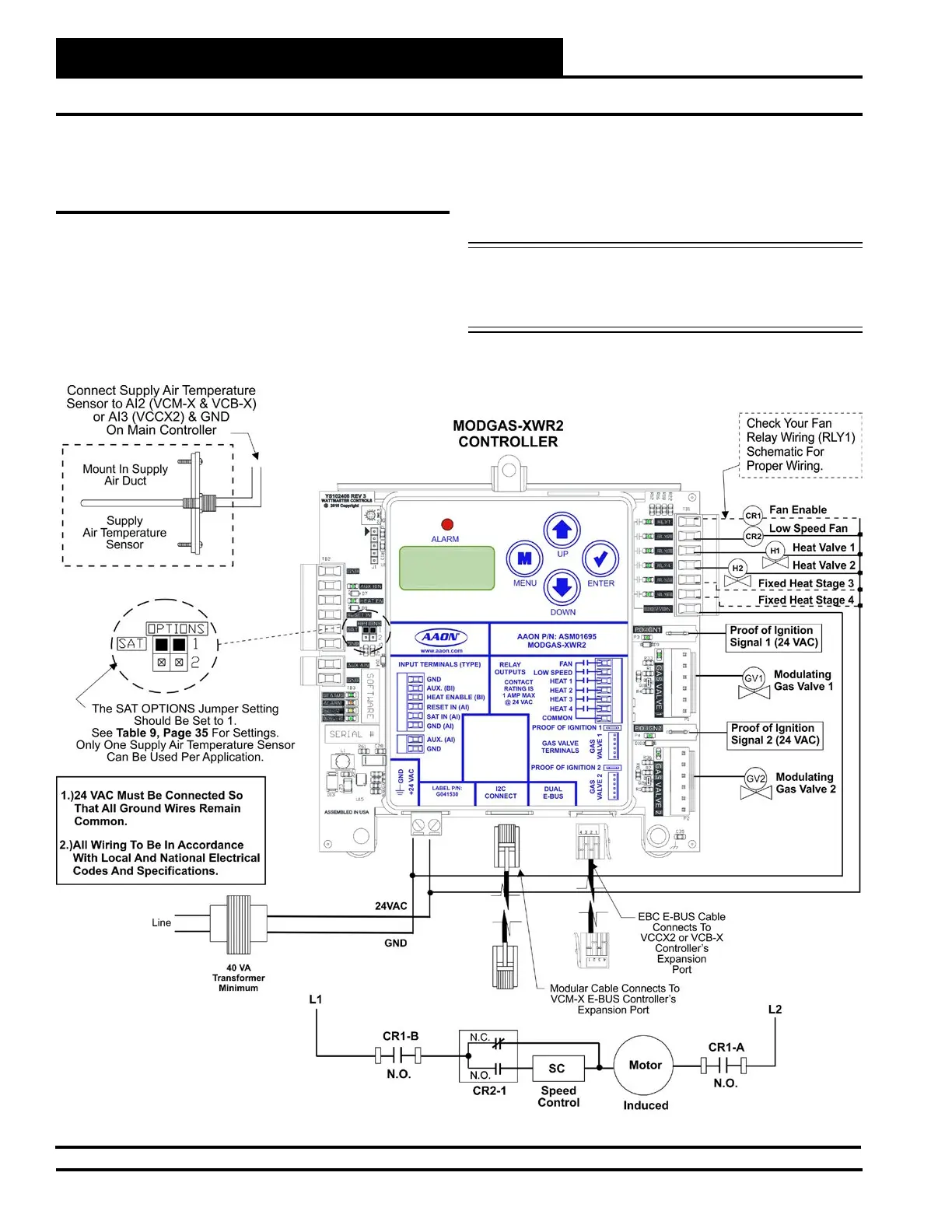
Figure 11: 2 Modulating Valves, 2 Ignitors, 2 Stage Communicating Wiring Diagram
2 Modulating Valves, 2 Ignitors,
2 Stages (2V2IGN2S) - Communicating
Wiring
This conguration operates as Stand-Alone (Figure 3, page 6) or
communicating with an AAON Unit Controller (Figure 11, below).
This conguration is used to control two modulating gas valves (one
on each header), in which the rst valve is modulating stage 1 (valve
1 header) and the second valve is modulating stage 2 (valve 2 header).
The rst valve is attached to Heat Relay 1 and the second valve is at-
tached to Heat Relay 2.
For VCM-X Controllers, use an I
2
C Cable connecting to the appropriate
I
2
C port on the controller.
For all other controllers, use an E-BUS cable connecting to an E-BUS
port on the controller.
NOTE: Up to 2 additional xed heat stages can be used by using
Heat Relays 3 & 4 below. If additional xed stages are
required, these should be congured and wired to the
AAON Unit Controller’s relays.
 Loading...