Zone
Zone
STAND-ALONE WIRING
MODGAS-XWR2 Technical Guide
6
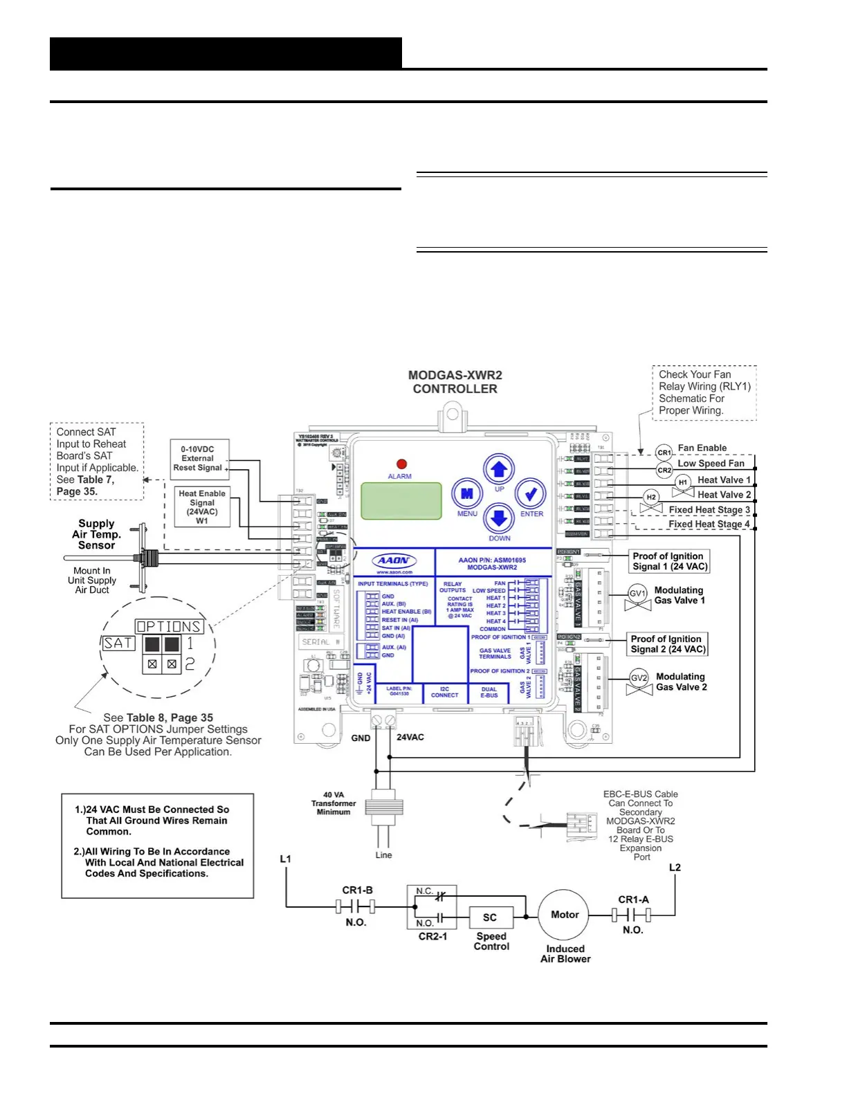
2V2IGN2S - Stand-Alone Wiring
Figure 3: 2 Modulating Valves, 2 Ignitors, 2 Stages Stand-Alone Wiring Diagram
2 Modulating Valves, 2 Ignitors,
2 Stages (2V2IGN2S) - Stand-Alone
Wiring
This configuration operates as Stand-Alone (Figure 3, below) or
communicating with an AAON Unit Controller (Figure 11, page 14).
This conguration is used to control two modulating gas valves (one
on each header), in which the rst valve is modulating stage 1 (valve
1 header) and the second valve is modulating stage 2 (valve 2 header).
The rst valve is attached to Heat Relay 1 and the second valve is at-
tached to Heat Relay 2.
NOTE: Up to 2 additional xed heat stages can be used by using
Heat Relays 3 & 4 below and up to 12 more additional
xed stages can be added by using the 12-Relay E-BUS
Expansion Module. (Figure 8, page 11).
If using an MHGRV-X Controller along with the MODGAS-XWR2
Controller in Stand-Alone, the SAT Sensor always attaches to the
MODGAS-XWR2 Controller.
 Loading...


