HW © 2015 Aaronia AG, DE-54597 Strickscheid, www.aaronia.com, mail@aaronia.de
10
Manual RF Signal-
Generator
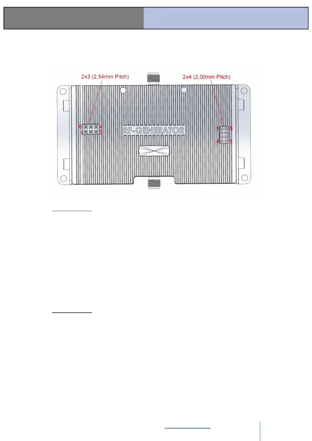
3.3. Pin-Layout OEM Versions
Connector 2X3:
• Pin 1: "Lock Detect" Output; 3,3V, max 10mA (Anode; Can
connect directly to a LED, other PIN needs to connect to GND)
• Pin 2: 12V DC in (Charge Input, needs 1A = 12W)
• Pin 3: "Power ON" Output; 3,3V, max 10mA (Anode; Can connect
directly to a LED, other PIN needs to connect to GND)
• Pin 4: "Battery Charge Finished" output, 3,3V, max 10mA (Anode;
Can connect directly to a LED, other PIN needs to connect to GND)
• Pin 5: "On/OFF and Start/Stop"; TTL, with low level (0V) (Can
also be used to directly connect a Push Button) Switch the
Generator On/Off or Start/Stop the batch programs
• Pin 6: GND
Connector 2X4:
• Pin 1: USB 5V (For USB)
• Pin 2: USB- (For USB)
• Pin 3: USB+ (For USB)
• Pin 4: "Battery Charging" output, 3,3V, max 10mA (Anode; Can
connect directly to a LED, other PIN needs to connect to GND)
• Pin 5: GND (For USB)
• Pin 6: GND (For USB)
• Pin 7: GND (For USB)
• Pin 8: GND (For USB)
ООО "Техэнком" Контрольно-измерительные приборы и оборудование www.tehencom.com