P. 32 - Chap. 6 Handling and installation
G
B
The machine cooling air and the heating ducts
(where relevant) must be dimensioned so that
air speed does not exceed 3 m/s. The maxi-
mum length of the ducts is 6 m. If this is not so,
fit an
auxiliary fan in the hot air duct.
Following installation of the hot air ducts, check that any back pressure, measured at the outfeed of
the hot air from the compressor, does not exceed 5-6 mm of water column.
For guidance purposes, duct cross-section area should be equal to that of the compressor hot air outlet grill
(reference FU in Figs. 14, 16, 18, 20, 22, 24).
Heat the environment if the minimum temperature required cannot be guaranteed.
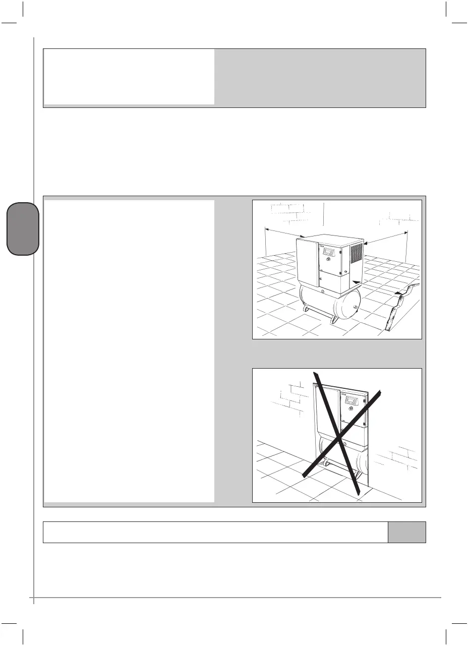
Comply with the minimum distances from the
walls shown in figure 31
The position of the compressor in the room
should allow easy inspections. If the compres
-
sor is installed in the working environment,
keep at suitable safety distance according to
the type of process carried out at the premises
in order to prevent hazards or damage to the
machine due to the products used.
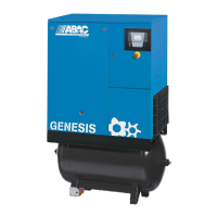
The compressor should not be installed in a
recess which does not allow correct ventila
-
tion. Hot air flow should not be obstructed in
any way and recirculation must be prevented
(Fig. 32).
Fig. 31
Fig. 32
600
600
600
6.3
Air connection
When connecting the compressor to the receiver or to the distribution line, it is good practice to insert a hose
of suitable size and specifications (pressure and temperature) connected to the
MA sleeve (Figs. 14, 16, 18,
20, 22, 24). The compressed air lines must be in perfect conditions and suitably fastened.