openopen
No damage will occur when the plug is inserted 180 degrees turned.
110-250 VDC
100-240 VAC
The input has a rectifier bridge
Correct / 180 degrees wrong
Correct
180 degrees wrong
No problem, contact open
48-125 VDC
1 2 3
1 2 3
1 2 3
GUID-C2321B6B-3157-4F0A-AD25-ACE8E71C4462 V2 EN
Figure 32: Connecting the auxiliary voltage connector
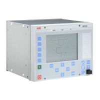
5.7 Connecting communication
Before connecting communication, check that the HW module has the correct
communication interfaces. The communication module is located at the bottom of
the IED for the 4U half 19” case and on the left side of the IED for the 6U half 19”
case when viewing the case from the rear.
See the technical manual for product-specific communication
interfaces.
The allowed minimum bending radius has to be checked from the
optical cable manufacturer.
Ethernet devices shall not be connected into rear HMI port. This
can damage IED or connected Ethernet device.
Section 5 1MRS755958 C
Connecting
60 630 series
Installation Manual
 Loading...