IEC12000612 V1 EN
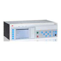
Figure 43: Local HMI: Placement of local HMI operation elements
Function block LEDGEN
• Handles an external acknowledge signal as source to acknowledge the LEDs.
• Generates an additional pulse for general purposes whenever the LEDs are
acknowledged by the operator.
• Generates a pulse whenever a new LED signal occurs. It may be used to trigger
an acoustical alarm.
• Handles the timer tReset and tMax for the LED operation mode 'LatchedReset-S'.
Function block GRP1_LED1 to GRP3_LED15
• The 15 LEDs on the right side of the LCD can indicate in total 45 alarms,
warnings or other signals to the operator. They are organized in three groups 1 to
3.
• Each signal group belongs to one function block.
• Each LED illuminates in one of the three colors: RED, YELLOW or GREEN.
• The organization of flashing, acknowledgment and group selection is done
directly between the function blocks and the basic LHMI keys, the 'Multifunction'
key [a] to toggle between the three groups or the 'Clear' key [b] to acknowledge
or reset the LEDs.
• Only the programming of the signals is needed for the LEDs.
• The operation mode of the LEDs is defined in Parameter Setting tool.
Function block FNKEYMD1 to 5
• Every function key has an own FNKEYMD function block.
• The 5 function keys on the left side of the LCD [B] can be used to process
demands.
• The function block handles the signal for the LED included in the key as input
signals.
• The LED signal of the key is independent of the key function and must be
programed to process demands.
• The function block handles the operators command when the key is pressed as
output signal.
• The functions are activated whenever a key is pressed the first time. The
corresponding text elements for the five keys appear on the left side of the LCD.
1MRK 511 284-UEN A Section 6
Local HMI engineering
650 series 65
Engineering manual
 Loading...


