Operation Manual / A100-L
3 Removal and installation / 3.3 Installing the turbocharger
© Copyright 2021 ABB. All rights reserved. HZTL4034_EN Rev.T December 2021
3.3.2 Steps for fastening the turbocharger
General information
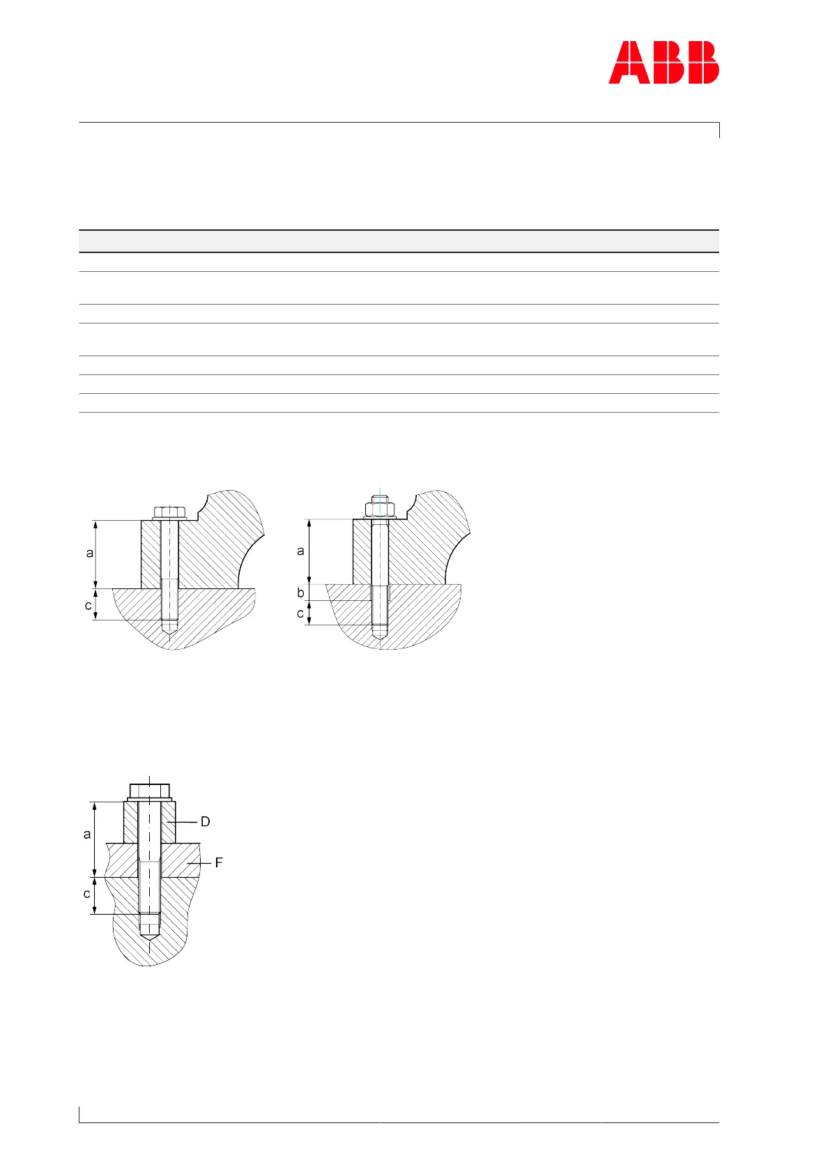
Subject Requirement / Information
Turbocharger fixing elements ISO property class ≥ 8.8
Washers Hardened, thickness ≥15% nominal thread dia-
meter
Dimension a (compressor end) a = height of turbocharger foot a
Dimension a (turbine end) a = height of turbocharger foot F + spacer sleeve
D
Dimension b Hole in bracket
Dimension c Thread length, ≥ 1.5 x nominal thread diameter
Coefficient of friction 0.12 (lightly oiled)
Table4: General information about fastening the turbocharger
Compressor-end foot
Fig.9: Compressor-end foot
u Tighten the foot fixing screws or nuts diagonally according to the selected tightening
method.
Turbine-end foot
Fig.10: Turbine-end foot
u Tighten the foot fixing screws or nuts according to the selected tightening method.
Page 28 / 141
 Loading...