ABB Chapter 12 - Replacing Printed Circuit Boards
ACS 6000 Maintenance Manual 3BHS202077 ZAB E01 Rev. C 12-13 (14)
CVMI Boards are installed in the following cabinets:
•ARU
•INU
In converters with power ratings above 7 MVA, the CVMI board is mounted
on the back side of the hinged cover of the cable duct in the top section of
the ARU cabinet. To access the board the cover must be opened. See
Figure 12-8
.
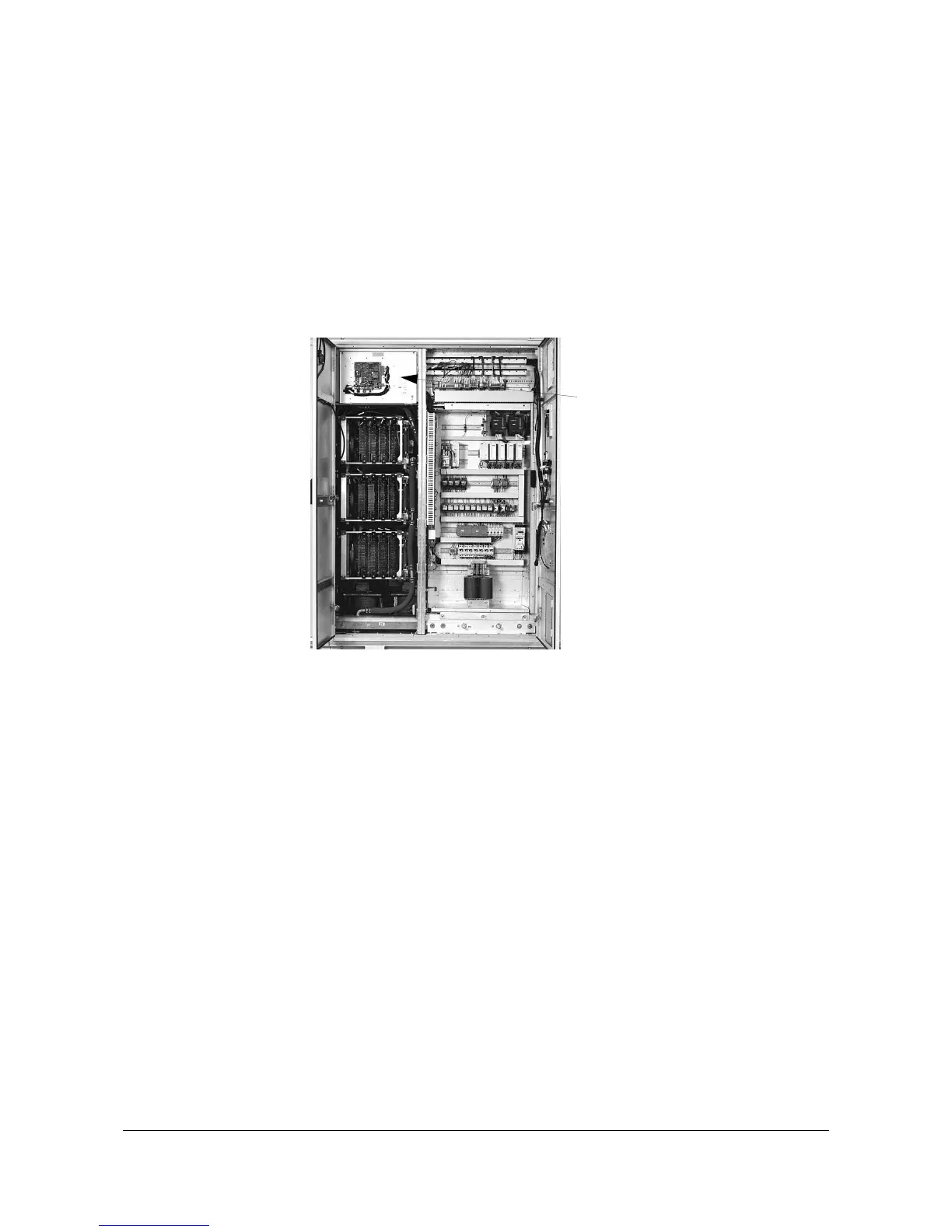
In 3/5 MVA converters the CVMI board is mounted on the front of the
hinged cover. See
Figure 12-12
.
Figure 12-12 Location of CVMI Board in 3/5 MVA Concerters
1 Before touching the CVMI board ground yourself at the converter
frame with a wrist strap.
2 Remove the power and ground the ACS 6000 according to section
12.1 Safety
.
3 Unplug the fiber optic cables and all other connectors.
4 Remove the fastening screws (7 pcs).
Take all necessary precautions to prevent that srews and washers fall
into other components.
5 Remove the CVMI board and place it on a grounded working surface
protected against electrostatic discharges to transfer the SVA and
SCA board to the new CVMI board. The location of the printed circuit
boards can be seen in
Figure 12-11
.
6 Remove the sub-boards and install them on the new board.
7 Attach the new CVMI board with all fastening screws.
8 Reconnect all cables.
CVMI board