53 ACS2000 AFE 1MVA UM 3BHS297030 ZAB E01 REV. J
Parameters
The control system is configured, customized, and
tuned with a set of application parameters. The
application parameters are organized in functional
groups and have factory-set default values.
The default parameter values are adjusted during
commissioning to the specific application of the
drive to activate the specific control, monitoring
and protection functions for the driven process,
and to define the signals and data to be trans-
ferred between drive and external equipment.
The parameters and parameter groups referred to
in the signal allocation tables in this chapter are
valid for drives with software version LDOI6xxx
revision "-" and later versions.
Main circuit breaker
The main circuit breaker (MCB) is
an important switching and pro-
tection device of the drive system.
Therefore it must only be con-
trolled and monitored by the
drive.
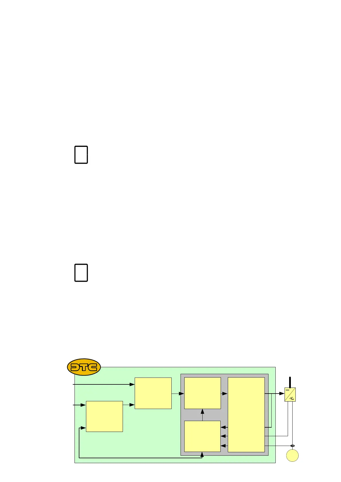
Direct torque control
The speed and torque of the motor is controlled by
DTC (Direct Torque Control). DTC provides accu-
rate speed and torque control, and high dynamic
speed response.
Switching of the semiconductors in the INU is
directly controlled in accordance with the motor
core variables flux and torque.
The measured motor currents and DC link voltages
are inputs to an adaptive motor model. The model
produces exact values of torque and flux every 25
microseconds. Motor torque and flux comparators
compare the actual values to reference values
which are produced by the torque and flux refer-
ence controllers.
Depending on the outputs from the hysteresis con-
trollers, the switching logic directly determines the
optimum switch positions every 50 microseconds
and initiates switching whenever required.
Peripheral I/O devices
The peripheral input and output devices connected
to the AMC circuit board of the INU include:
•Local CDP control panel
• I/O interfaces for parallel signal transfer to exter-
nal devices
• Optional fieldbus adapters for serial data trans-
fer to a higher-level control system
• PC-based service tools comprising:
-DriveWare
®
software tools
DriveWare
®
includes software tools such as
the commissioning and maintenance tools
DriveWindow and DriveDebug, and
DriveOPC for data transfer between ABB
drives and Windows
®
-based applications.
-DriveMonitor
(option)
DriveMonitor is a monitoring and diagnos-
tics tool that allows access to the drive from
any location in the world via a secure inter-
net connection.
For further information on the parame-
ters for signal allocation, signal type
selection, signal inversion, scaling, and fil-
tering, see signal and parameter table.
For further information, see:
• Main circuit breaker engineering
guideline
• Important note on main circuit
breaker
3-5 Direct torque control
3-5
Speed
controller
Torque-
reference
controller
Torque
flux
comparator
Motor
model
Switching
logic
Switch
positions
Voltage
Current
M
Torque reference
Speed reference
Actual speed
or