39
9.2. Parameters in the Short parameter mode
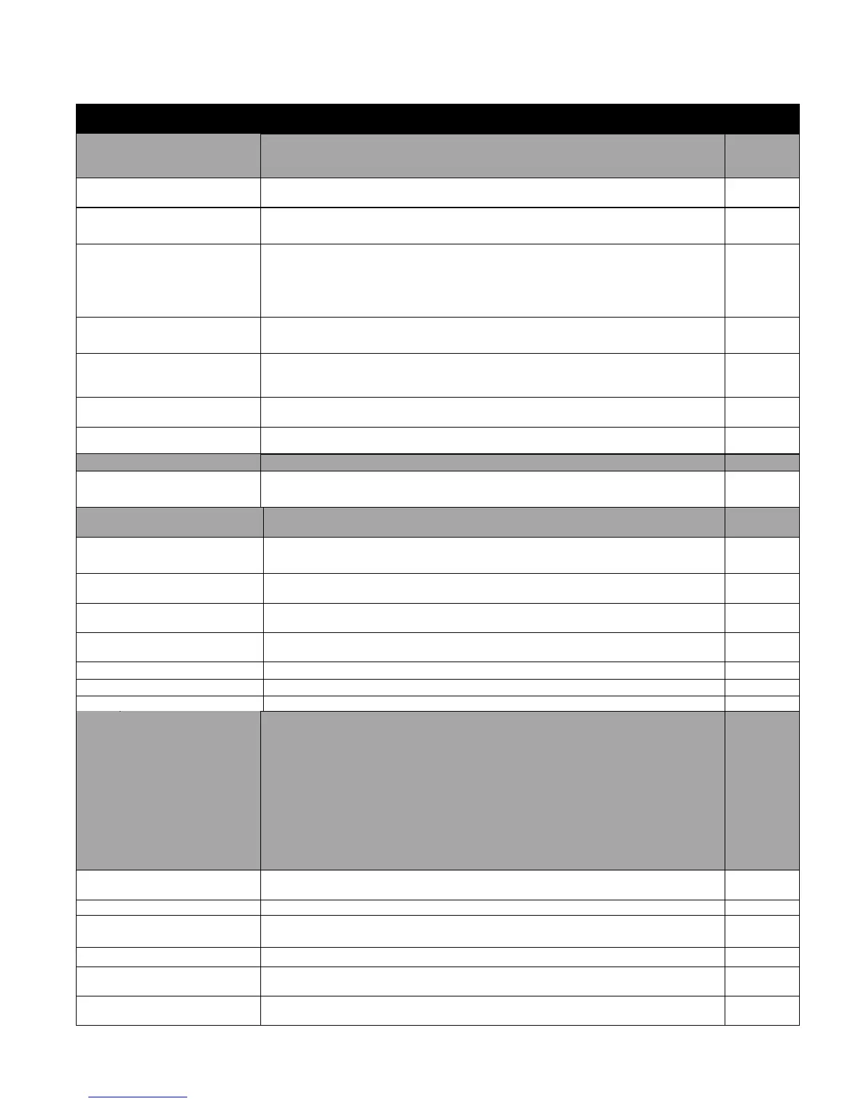
The following table describes the parameters that are visible in the Short parameter mode. See section 9.1 on page 38 for how to
select the parameter mode. All parameters are presented in detail in section Parameters in the Long parameter mode.
Parameters in the Short parameter mode
Application macros. Definition of motor set-up data.
As shown in section 8.1 Parameter 9902 has a number of pre-programmed parameter sets
(and terminal functions) which the user selects to best suit the application requirements.
DIGITAL INPUTS
FUNCTION SELECT
Defines the function of the digital inputs depending on the control mode setting in
Parameter 1103 PRIMARY COMMAND SOURCE MODE. (See section 8.1 for further detail)
This parameter should be set to the rated (nameplate) voltage of the motor (Volts).
Voltage
Note : The stress on the motor insulation is always dependant on the drive supply voltage.
This also applies in the case where the motor voltage rating is lower than the rating of the
drive and the supply of the drive.
This parameter should be set to the rated (nameplate) current of the motor.
0.2* drive rated output
current…1.0* drive rated
output current
This parameter should be set to the rated (nameplate) frequency of the motor
Fault history (read only)
Displays the last four fault codes for the drive. Refer to section 13.1 for further information
The drive can accept a variety of references in addition to the conventional analog input,
potentiometer and keypad signals.
PRIMARY COMMAND
SOURCE MODE
The drive responds directly to signals applied to the control terminals.
1: UNI-DIRECTIONAL
KEYPAD CONTROL
The drive can be controlled in the forward direction only using an external or remote Keypad.
2: BI-DIRECTIONAL
KEYPAD CONTROL.
The drive can be controlled in the forward and reverse directions using an external or remote
Keypad. Pressing the keypad START button toggles between forward and reverse.
The output frequency is controlled by the internal PI controller.
Control via CAN bus connected to the RJ45 serial interface connector
Constant speeds. Constant speed activation overrides the external speed reference. Constant
speed selections are ignored if the drive is in the local control mode.
Refer to section 8.1 for how to make constant speed selections from the drive control
terminals.
Preset Speeds / Frequencies selected by digital inputs depending on the setting of Parameter
9902.
If Parameter 9908 = 0, the values are entered as Hz. If Parameter 9908 > 0, the values are
entered as Rpm.
Setting a negative value will reverse the direction of motor rotation.
Preset / Jog Frequency /
Speed 1
Defines constant speed 1 (that is the drive output frequency)
Preset / Jog Frequency /
Speed 2
Defines constant speed 2 (that is the drive output frequency)
Preset / Jog Frequency /
Speed 3
Defines constant speed 3 (that is the drive output frequency)