41
9.3. Read Only Status parameters
9.3.1. Read Only Status parameter access and navigation.
The user must be in the Long Parameter group to gain access to the Read only status parameters. See section 9.1.1 for how to navigate to the
long parameter group.
In the Long Parameter Group when the user scrolls to parameter “0000”, pressing will display “0104”, the User can then scroll to the
required Read only status parameter (as listed in the table above). Pressing once more will then display the value of that particular Read
only status parameter.
For those parameters which have multiple values (e.g. software ID parameter 3301), pressing the and keys will display the different
values within that parameter.
Pressing returns to the next level up. If is then pressed again (without pressing or ), the display changes to the next level up
(main parameter level, i.e. Parameter “0000”).
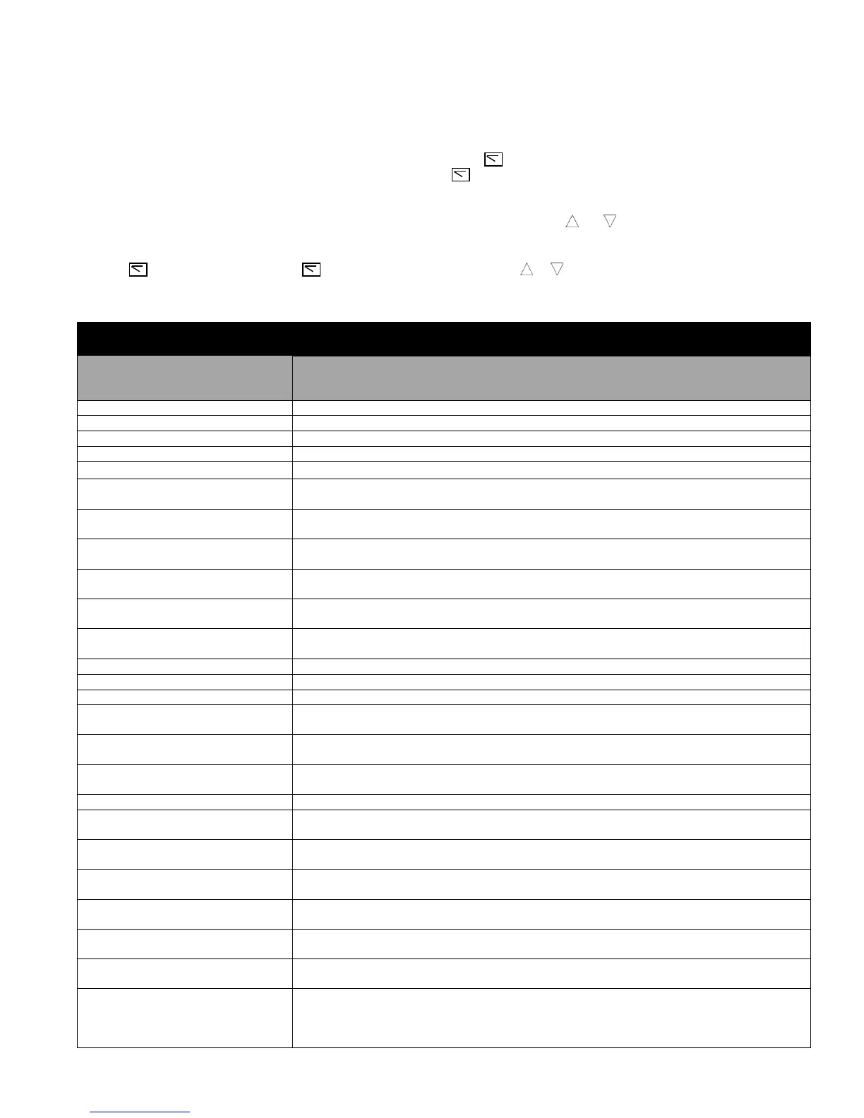
The following table includes the descriptions of all Read Only status parameters.
Basic signals for monitoring the drive (read-only).
For selection of an actual signal to be displayed on the control panel, see parameter 3405 DISPLAY
SCALING SOURCE.
In Vector control mode, this parameter displays the estimated rotor speed of the motor.
Displays the instantaneous output torque level produced by the motor in %.
Displays the instantaneous DC Bus Voltage internally within the drive in V DC.
Displays the instantaneous output voltage from the drive to the motor V AC.
Displays the Instantaneous Heatsink Temperature measured by the drive in ˚C.
PRE RAMP SPEED CONTROLLER
REFERENCE
Displays the set point reference input applied to the drive internal speed controller in Hz.
TORQUE CONTROLLER
REFERENCE
Displays the set point reference input applied to the drive internal torque controller in %.
DIGITAL SPEED REFERENCE
(MOTORISED POT)
Displays the value of the drive internal Motorised Pot (used for keypad) speed reference in Hz.
ENERGY CONSUMPTION kWh
METER
Displays the amount of energy consumed by the drive in kWh. When the value reaches 1000, it is reset
back to 0.0, and the value of Parameter 0141 (*MWh meter) is increased.
ANALOG INPUT 1 APPLIED
SIGNAL LEVEL
Displays the signal level applied to analog input 1 (Terminal 6) in % after scaling and offsets have been
applied.
ANALOG INPUT 2 APPLIED
SIGNAL LEVEL
Displays the signal level applied to analog input 2 (Terminal 10) in % after scaling and offsets have been
applied.
Displays the output level of the PI controller in %.
Displays the setpoint input to the PI controller in %.
Displays the Feedback input signal to the PI controller in %.
FIELDBUS COMMUNICATION
SPEED REFERENCE
Displays the setpoint being received by the drive from the currently active Fieldbus interface in Hz.
DRIVE LIFETIME OPERATING
TIME
Displays the total operating time of the drive. The first value shown is the number of hours. Pressing
the Up key will display the minutes and seconds. (HH:MM:SS)
ENERGY CONSUMPTION MWh
METER
Displays the amount of energy consumed by the drive in MWh.
Displays the status of the drive inputs, starting with the left hand side digit = Digital Input 1 etc.
MOTOR MAGNETISING
CURRENT (Id)
Displays the motor magnetising Current in AMPS providing an auto tune has been successfully
completed.
Displays the motor Rotor (torque producing) current in Amps, providing an auto tune has been
successfully completed.
DC BUS VOLTAGE RIPPLE LEVEL
Displays the level of ripple present on the DC Bus Voltage in V DC. This parameter is used by the
ACS255 for various internal protection and monitoring functions.
MOTOR STATOR RESISTANCE
(Rs)
Displays the measured motor stator resistance in ohms, providing an auto tune has been successfully
completed.
MOTOR STATOR INDUCTANCE
(Ls)
Displays the measured motor stator inductance in H, providing an auto tune has been successfully
completed.
MOTOR ROTOR RESISTANCE
(Rr)
Displays the measured motor rotor resistance in ohms, providing an auto tune has been successfully
completed.
OPERATING TIME
ACCUMULATED WITH
HEATSINK TEMPERATURE
ABOVE 80°C
Displays the amount of time in hours and minutes that the ACS255 has operated for during its lifetime
with a heatsink temperature in excess of 80°C. This parameter is used by the ACS255 for various
internal protection and monitoring functions. (HH:MM:SS)