Technical data
39
Sizing
The current ratings are the same regardless of the supply voltage within one voltage range. To achieve
the rated motor power given in the table, the rated current of the drive must be higher than or equal to
the rated motor current.
Note 1: The maximum allowed motor shaft power is limited to 1.5 · P
N
. If the limit is exceeded, motor
torque and current are automatically restricted. The function protects the input bridge of the drive
against overload.
Note 2: The ratings apply at ambient temperature of 40°C (104°F).
Derating
The load capacity decreases if the installation site ambient temperature exceeds 40°C (104°F) or if the
altitude exceeds 1000 meters (3300 ft). Derating is not allowed.
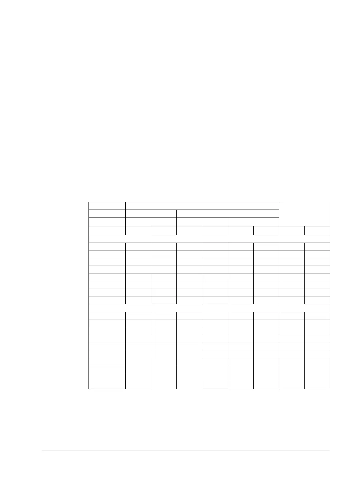
Cooling air flow requirements
The table below specifies the heat dissipation in the main circuit at nominal load and
in the control circuit with minimum load (I/O and panel not in use) and maximum load
(all digital inputs in the on state and the panel, fieldbus and fan in use). The total heat
dissipation is the sum of the heat dissipation in the main and control circuits.
Type Heat dissipation Air flow
ACS350- Main circuit Control circuit
x = E/U Rated I
1N
and I
2N
Min Max
W BTU/Hr W BTU/Hr W BTU/Hr m
3
/h ft
3
/min
3-phase U
N
= 200…240 V (200, 208, 220, 230, 240 V)
03x-02A4-2 19 65 6.1 21 22.7 78 - -
03x-03A5-2 31 106 6.1 21 22.7 78 - -
03x-04A7-2 38 130 9.5 32 26.4 90 - -
03x-06A7-2 60 205 9.5 32 26.4 90 - -
03x-07A5-2 62 212 9.5 32 26.4 90 - -
03x-09A8-2 83 283 10.5 36 27.5 94 - -
03x-13A3-2 112 383 10.5 36 27.5 94 - -
03x-17A6-2 152 519 10.5 36 27.5 94 - -
3-phase U
N
= 380…480 V (380, 400, 415, 440, 460, 480 V)
03x-01A2-4 11 38 6.6 23 24.4 83 - -
03x-01A9-4 16 55 6.6 23 24.4 83 - -
03x-02A4-4 21 72 9.8 33 28.7 98 - -
03x-03A3-4 31 106 9.8 33 28.7 98 - -
03x-04A1-4 40 137 9.8 33 28.7 98 - -
03x-05A6-4 61 208 9.8 33 28.7 98 - -
03x-07A3-4 74 253 14.1 48 32.7 112 - -
03x-08A8-4 94 321 14.1 48 32.7 112 - -
03x-12A5-4 130 444 12.0 41 31.2 107 - -
03x-15A6-4 173 591 12.0 41 31.2 107 - -
00353783.xls G